Step attenuator apparatus

a technology of attenuator and step, which is applied in the direction of waveguide type devices, coupling devices, basic electric elements, etc., can solve the problems of increasing circuit area, increasing cost, and increasing the number of components

Inactive Publication Date: 2011-12-29
ADVANTEST CORP
View PDF1 Cites 128 Cited by
  • Summary
  • Abstract
  • Description
  • Claims
  • Application Information

AI Technical Summary

Benefits of technology

[0024]By setting the step attenuator apparatus to the disconnected state, embodiments such as these provide a n...

Problems solved by technology

Such a switch leads to an increased number of components, in...

Method used


Image

  • Step attenuator apparatus
  • Step attenuator apparatus
  • Step attenuator apparatus

Examples


Embodiment Construction

[0030]The invention will now be described based on preferred embodiments which do not intend to limit the scope of the present invention but exemplify the invention. All of the features and the combinations thereof described in the embodiment are not necessarily essential to the invention.

[0031]In the present specification, the state represented by the phrase “the member A is connected to the member B” includes a state in which the member A is indirectly connected to the member B via another member that does not substantially affect the electric connection therebetween, or that does not damage the functions or effects of the connection therebetween, in addition to a state in which the member A is physically and directly connected to the member B. Similarly, the state represented by the phrase “the member C is provided between the member A and the member B” includes a state in which the member A is indirectly connected to the member C, or the member B is indirectly connected to the m...


PUM


Abstract

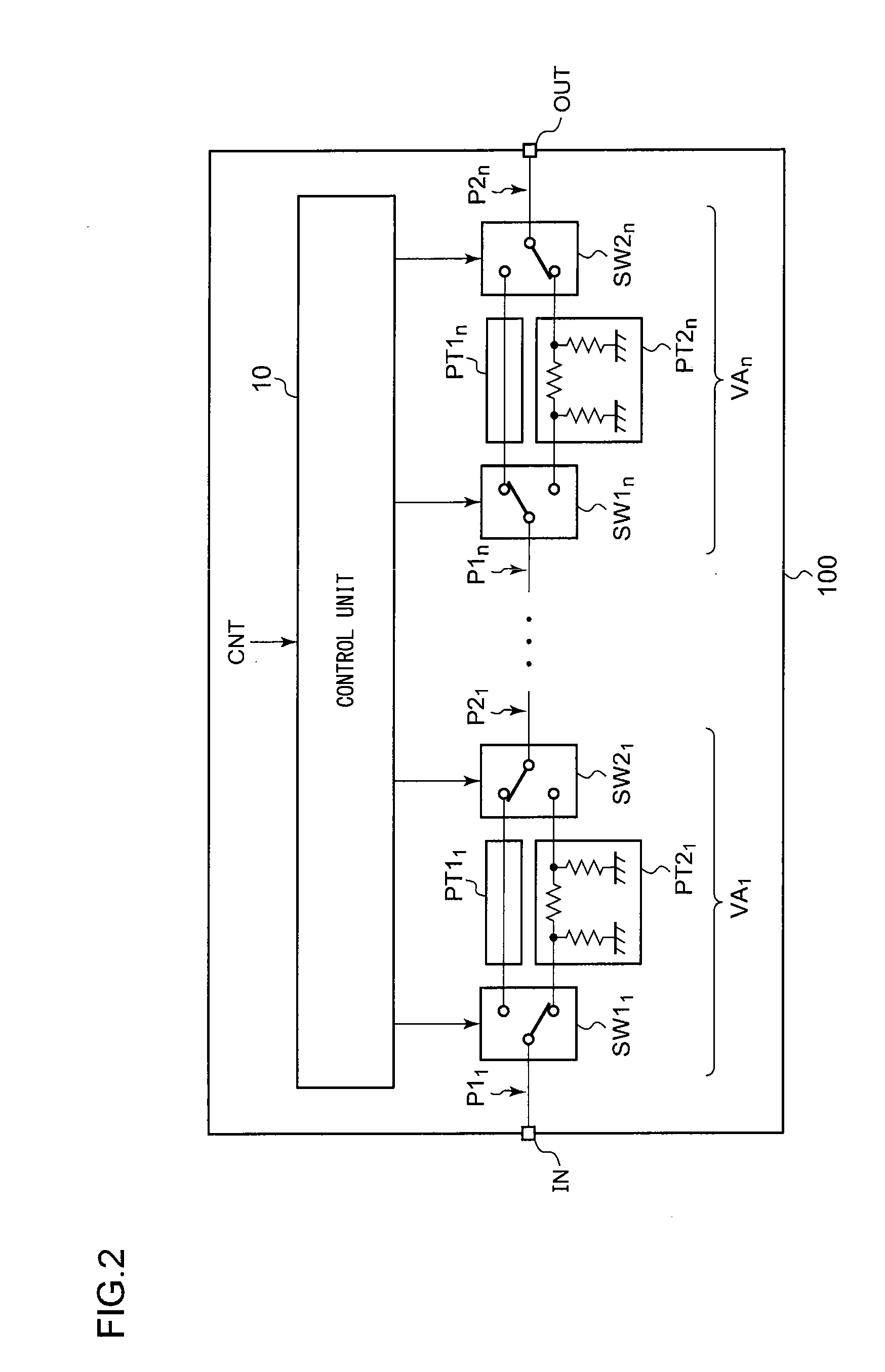
A step attenuator apparatus is provided, having an attenuation ratio which is switchable according to a control signal. Multiple variable attenuators are connected in series. Each variable attenuator includes a first terminal, a second terminal, multiple paths having different attenuation ratios, a first switch that can be connected to one end of a desired path selected from among the multiple paths, and a second switch that can be connected to the other end of a desired path selected from among the multiple paths. When a control signal is an instruction to set the step attenuator apparatus to a disconnected state, a control unit connects the first switch of the first-stage variable attenuator to one of the multiple paths, and connects the second switch of the first-stage variable attenuator to a different one of the multiple paths.

Description

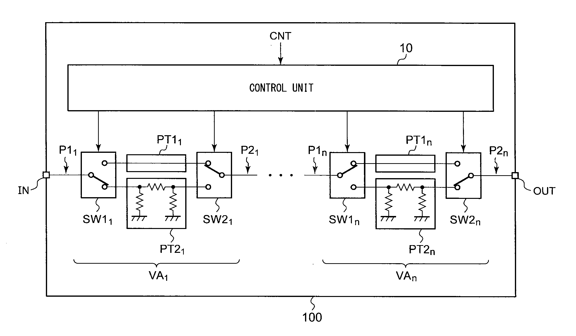
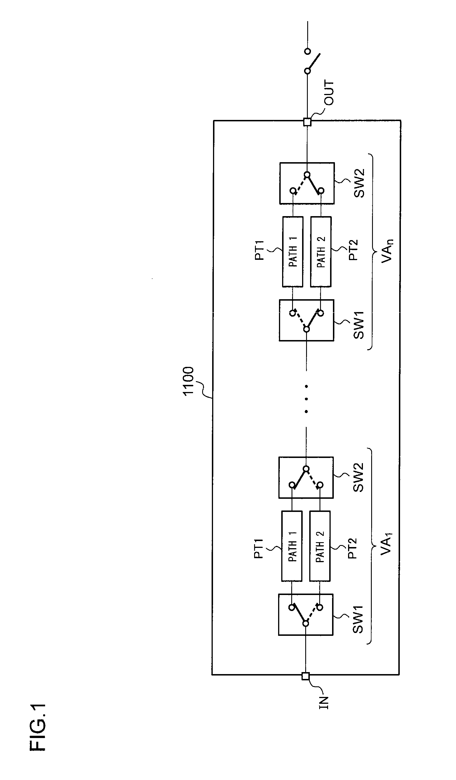
BACKGROUND OF THE INVENTION[0001]1. Field of the Invention[0002]The present invention relates to a step attenuator apparatus.[0003]2. Description of the Related Art[0004]A step attenuator apparatus is known wherein the overall attenuation amount is switchable by switching the internal path by means of switches. FIG. 1 is a circuit diagram which shows a configuration of a typical step attenuator apparatus. A step attenuator apparatus 1100 includes multiple variable attenuators VA1 through VAn connected in series.[0005]Each variable attenuator VA includes multiple paths PT1 and PT2 and switches SW1 through SW2. The paths PT1 and PT2 have different attenuation ratios. For example, the path PT1 has an attenuation ratio of 0 dB (through path), and the path PT2 has a non-zero attenuation ratio (20 dB).[0006]With such an attenuator apparatus 1100, the two switches SW1 and SW2 included in the same variable attenuator VA can only be connected to the same path PT. Accordingly, with the attenu...

Claims


Application Information

Patent Timeline
IPC IPC(8): H01P1/22
CPCH01P1/22
Inventor TAKEUCHI, HIROAKI
Owner ADVANTEST CORP
Why Eureka
Try Eureka