Method and apparatus for reporting channel state in multi-carrier system
Active Publication Date: 2011-12-29
LG ELECTRONICS INC
View PDF9 Cites 93 Cited by
Summary
Abstract
Description
Claims
Application Information
AI Technical Summary
This helps you quickly interpret patents by identifying the three key elements:
Problems solved by technology
Method used
Benefits of technology
Benefits of technology
[0017]While the structure of the existing 3GPP LTE remains intact, a channel condition for a plurality of carriers can be reported. A channel condition for a plurality of carriers can be reported without an additional uplink grant.
Problems solved by technology
In a multi-carrier system, however, it may be inefficient if the channel structure of the single carrier system is used without change.
If CQIs for all the carriers are reported, however, radio resources may be inefficiently used.
Method used
Image
Click on the blue label to locate the original text in one second.
Reading with bidirectional positioning of images and text.
Examples
first embodiment
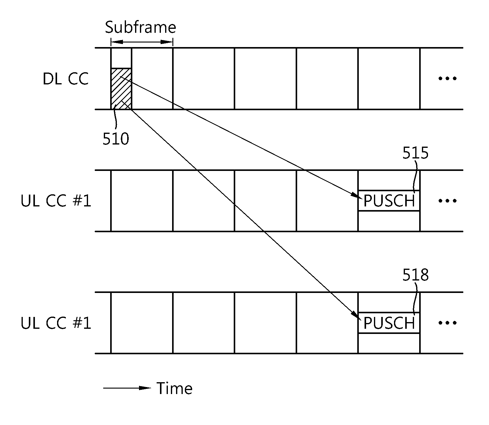
[0084]As a first embodiment, a CQI for a DL CC through which an uplink grant is transmitted is reported. This is assumed to be a reference DL CC. Here, there is a linked UL CC linked to the reference DL CC. The linked UL CC is an UL CC through which a PUSCH is transmitted using the uplink grant. There may be the linked UL CC and a plurality of linked DL CCs. UE reports a CQI for the plurality of DL CCs.
[0085]For example, it is assumed that there are a DL CC #1, a DL CC #2, a DL CC #3, a DL CC #4, a DL CC #5, and an UL CC #1 and an UL CC #2. It is also assumed that the UL CC #1 is linked to the DL CC #1, the DL CC #2, and the DL CC #3, and the UL CC #2 is linked to the DL CC #4 and the DL CC #5. In the ‘link’, an uplink grant received through the DL CC #1, the DL CC #2, or the DL CC #3 is used by the linked UL CC #1. If an uplink grant including a CQI request is received through the DL CC #1, a UE sends a CQI for not only the DL CC #1, but also the DL CC #2 and the DL CC #3.
[0086]The...
second embodiment
[0087]As a second embodiment, a BS may inform UE of a report list regarding DL CCs whose CQI will be reported. The report list may be transmitted through part of system information or through higher layer signaling, such as an RRC message.
third embodiment
[0088]As a third embodiment, the CQI request may include information about a DL CC whose CQI will be reported. For example, an uplink grant may be configured as in Table 3 below.
TABLE 3FIELD NAMEDESCRIPTIONUplink resource allocationResource allocation for PUSCHCQI request index 1Index of first DL CC whose CQI will bereportedCQI request index 2Index of second DL CC whose CQI will bereported
[0089]The index of a DL CC whose CQI will be reported may be a physical index or a logical index. The CQI index 2 may be a value relative to the CQI index 1.
[0090]Alternatively, a CQI request may include the bitmap of DL CCs whose CQI will be reported. For example, an uplink grant may be configured as in Table 4 below.
TABLE 4FIELD NAMEDESCRIPTIONUplink resource allocationResource allocation for PUSCHCQI request1 bit field to trigger CQI reportCQI report bitmapBitmap to indicate DL CC through whichCQI will be reported
[0091]An UL CC through which a PUSCH for an aperiodic CQI is transmitted may be an ...
PUM
Abstract
A method and an apparatus for reporting a channel state in a multi-carrier system are provided. User equipment receives an uplink grant including an uplink resource allocation and a channel quality indicator (CQI) request via one downlink carrier from among a plurality of downlink carriers. The user equipment reports CQIs for the plurality of downlink carriers via a plurality of subframes in accordance with the CQI request.
Description
TECHNICAL FIELD[0001]The present invention relates to wireless communication and, more particularly, to a method and apparatus for reporting a channel state in a wireless communication system supporting multiple carriers.BACKGROUND ART[0002]Wireless communication systems are widely deployed in order to provide various kinds of communication services, such as voice and data. In general, the wireless communication systems are multiple access systems which can share available system resources (e.g., bandwidths and transmission power) and support communication with multiple users. The multiple access systems may include, for example, a CDMA (code division multiple access) system, a FDMA (frequency division multiple access) system, a TDMA (time division multiple access) system, an OFDMA (orthogonal frequency division multiple access) system, and an SC-FDMA (single carrier frequency division multiple access) system.[0003]In a common wireless communication system, although the bandwidth of...
Claims
Application Information
Patent Timeline
Application Date:The date an application was filed.
Publication Date:The date a patent or application was officially published.
First Publication Date:The earliest publication date of a patent with the same application number.
Issue Date:Publication date of the patent grant document.
PCT Entry Date:The Entry date of PCT National Phase.
Estimated Expiry Date:The statutory expiry date of a patent right according to the Patent Law, and it is the longest term of protection that the patent right can achieve without the termination of the patent right due to other reasons(Term extension factor has been taken into account ).
Invalid Date:Actual expiry date is based on effective date or publication date of legal transaction data of invalid patent.

