
Enhanced reliability routing protocol

Inactive Publication Date: 2011-12-29
THALES SA
View PDF0 Cites 4 Cited by
  • Summary
  • Abstract
  • Description
  • Claims
  • Application Information

AI Technical Summary

Problems solved by technology

In the technical field of communication networks, one of the problems which arises is to find mechanisms for exchanges between routers which are at one and the same time reactive and economical as regards bandwidth used.
The difficulty consists in fact in rapidly establishing the topology of the routers, both in the setup phase and in the phase of modifying the components of the network (disappearance, appearance of routers, change of network hookup of the routers), while not flooding the networks with protocol exchanges which may consume a significant part of the available bandwidth.
Despite the effectiveness of these protocols, the tactical-network interconnection topologies currently known in the military field exhibit notably the drawback of exhibiting redundancy of the nodes between networks and of networks between nodes, thereby generating an increase in protocol exchanges.
In the case of low throughput networks (from 1 Kbit / s to a few tens of Kbits / s), the existing protocols known to the person skilled in the art are not designed to optimize the reduction in the quantity of protocol information exchanged, necessary for correct operation of low throughput networks.
Likewise, the disregard of the concepts of parallel or redundant networks between nodes gives rise to avalanche phenomena in certain protocols, thereby causing significant traffic.
The protocols mentioned hereinabove do not therefore make it possible to achieve economy of bandwidth.
Moreover, the risk of a high rate of losses of potential packets is disregarded by the existing protocols.
These protocols do not therefore make it possible to obtain fast convergence while exchanging a small quantity of information.

Method used


Image

  • Enhanced reliability routing protocol
  • Enhanced reliability routing protocol
  • Enhanced reliability routing protocol

Examples


Embodiment Construction

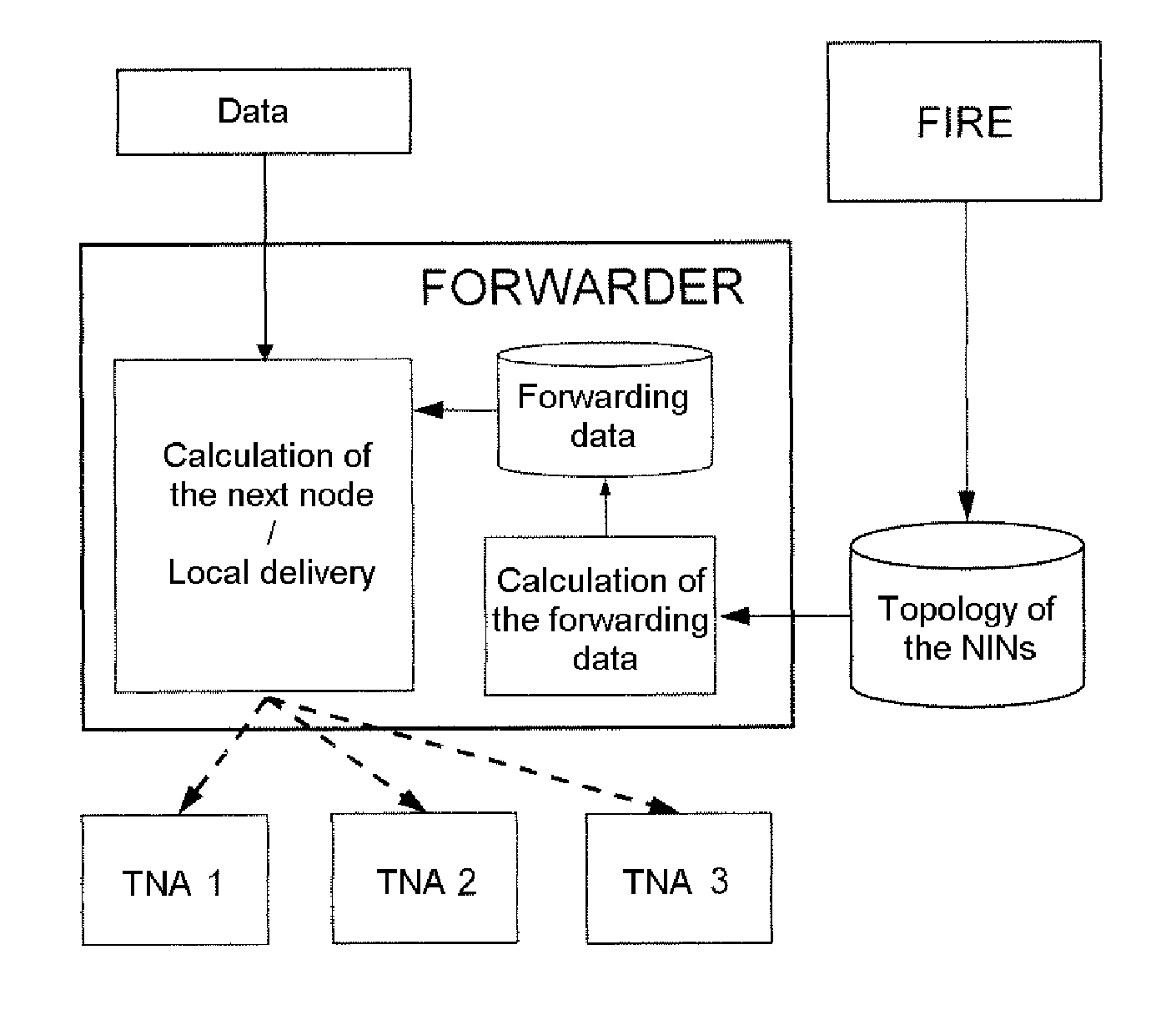
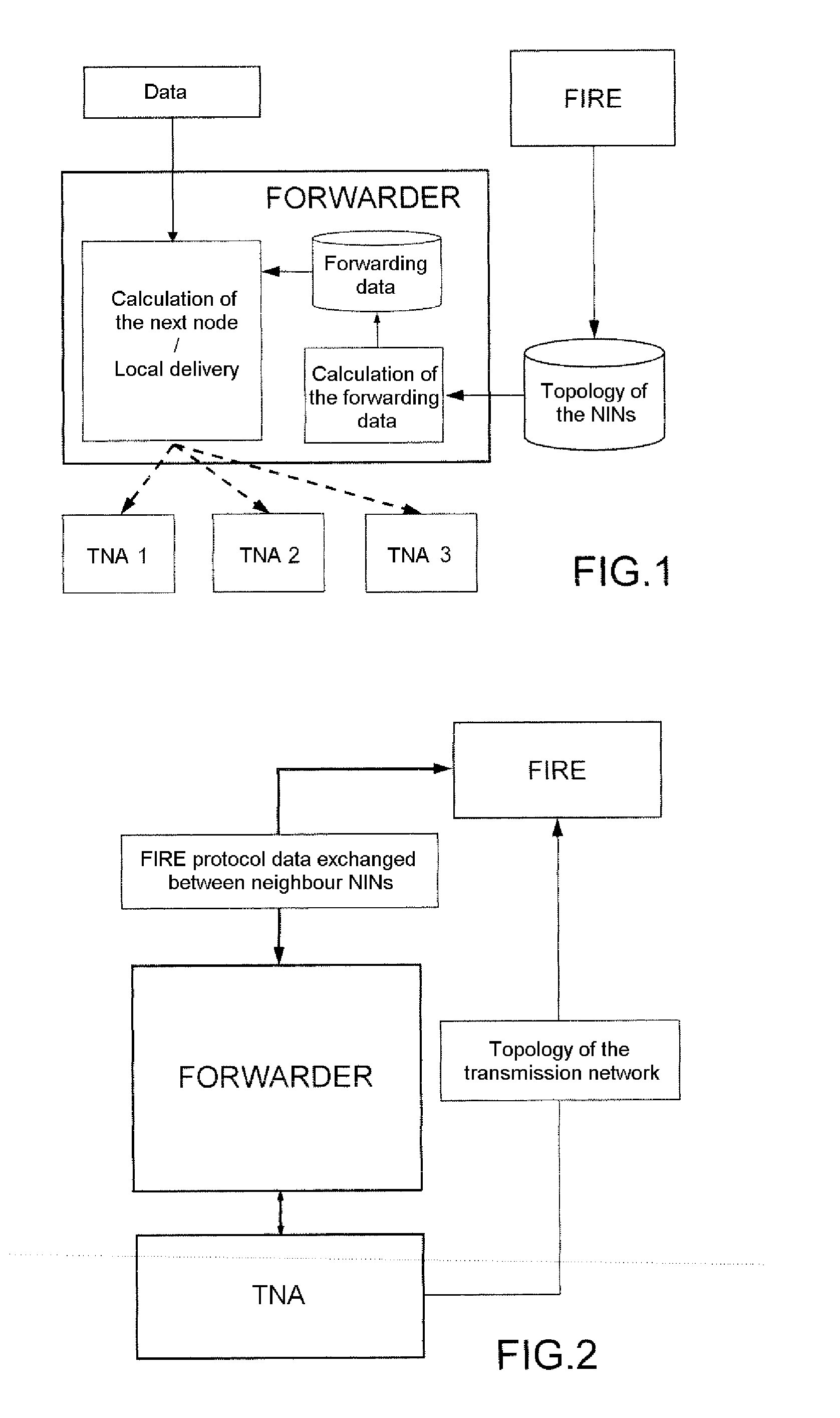
[0055]In the following detailed description of exemplary embodiments of a dynamic method of enhanced reliability routing according to the invention, the following apply:[0056]HYP_TOPO_1: The choice of the best route between a source ‘S’ and a destination ‘D’ for a data packet ‘P’ depends on several criteria. These criteria are hereinafter referred to as “routing criteria.”[0057]HYP_TOPO_2: For a route between a source ‘S’ and a destination ‘D’ for a data packet ‘P’, the value of each criterion can depend:[0058]on the nature and the state of the links traversed (a link is a logical connection between 2 nodes),[0059]on the characteristics and the state of the relay nodes traversed,[0060]on the parameters characterizing the data packets to be forwarded.

[0061]The routes depending on numerous criteria (HYP_TOPO—1), there exists a very large number of possible routes, each being the ‘best’ for a packet having given characteristics. The solution adopted for the protocol according to the in...


PUM


Abstract

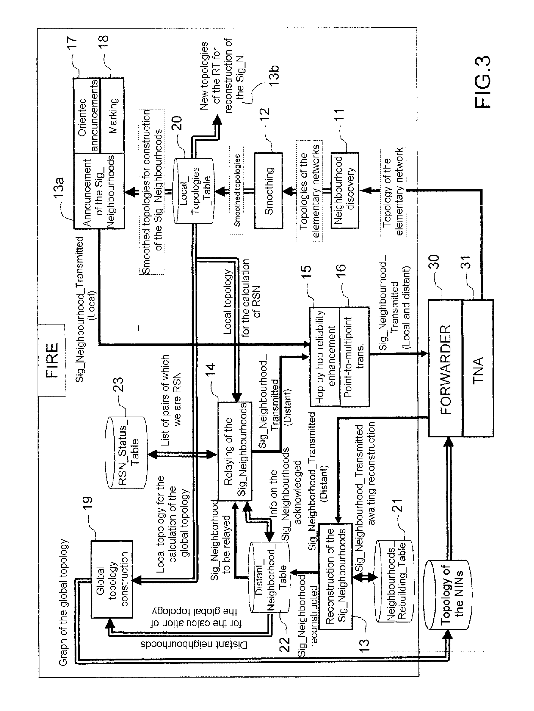
In a method of enhanced reliability routing within a system including one or more networks having several nodes connected together by communication means, the system using a link-state routing protocol constructing the topology of the nodes within a system of nodes, the routing method determines the logical topology of network interconnection nodes NIN by using modules which perform the following: discovery of the neighbourhood by functions of the physical networks; smoothing of the information provided by TNAs to improve the stability of the protocol; distributing the neighbourhoods to the set of NINs; relaying of the information associated with a node by a subset of the NIN node; hop by hop enhancement of the reliability of the transmission between various nodes; transmission in point-to-multipoint mode; announcement of oriented characteristics of logical links solely by the source routers of the links; marking of the signalling data so as to manage non-sequencing in reception; and calculation of the global topology.

Description

CROSS-REFERENCE TO RELATED APPLICATION[0001]This application claims priority to foreign French patent application No. FR 09 06215, filed on Dec. 21, 2009, the disclosure of which is incorporated by reference in its entirety.FIELD OF THE INVENTION[0002]The subject of the invention relates to a method of dynamic routing or routing protocol used in the field of low throughput networks operating in the 30 MHz-600 MHz bracket. The method according to the invention is used, for example, on nodes interconnecting several different physical networks, some of which are low throughput and high latency, such as VHF (Very High Frequency) radio networks. The protocol according to the invention or method of routing may be used in any UHF, VHF or other transmission network.BACKGROUND OF THE INVENTION[0003]In the technical field of communication networks, one of the problems which arises is to find mechanisms for exchanges between routers which are at one and the same time reactive and economical as...

Claims


Application Information

Patent Timeline
IPC IPC(8): H04L12/56
CPCH04L45/02
Inventor TESSIER, OLIVIERPEREZ, FREDERIC
Owner THALES SA
Learn More