Minimum contact area wafer clamping with gas flow for rapid wafer cooling

a technology of gas flow and minimum contact area, applied in the direction of electrical equipment, thin material processing, article separation, etc., can solve the problems of poor heat transfer, difficult to achieve, and the use of expensive venting gases by load locks, so as to shorten the required cooling time

Active Publication Date: 2011-12-29
NOVELLUS SYSTEMS
View PDF7 Cites 196 Cited by
  • Summary
  • Abstract
  • Description
  • Claims
  • Application Information

AI Technical Summary

Benefits of technology

[0007]The present invention provides a load lock where a wafer is separated from a cooling pedestal by no more than about 0.010 inch on average (over the surface of the wafer supported by the pedestal). Such small gaps allow use of inexpensive venting gases and shorten the required cooling time. Bowed wafers are flattened against the contact pins of a pedestal by a designed pressure differential between the front side and back side of the wafer. The differential is created by controlling the flow of the venting gas inside the load lock. This condition can be maintained by an inventive combination of dynamically controlling pressure distribution inside the load lock, venting gas ports (particularly their shape, position, and orientation), venting gas flow rates, flow paths, and other parameters.

Problems solved by technology

Rapid but uniform cooling is highly desired but is often difficult to achieve.
Since it is not practical to adjust the distances individually for each wafer, the separation distance must be set to non-optimum value (corresponding to the worst possible wafer deformation), resulting in generally poor heat transfer.
Thus, load locks employ expensive venting gases such as helium, which has a high heat transfer coefficient, and even then prolonged cooling periods are required.
A non-uniform gap between the cooling surface and the wafer also causes uneven cooling, leaving a hot spot in the areas bowing up (away) from the cooling surface, which could cause excessive stress possibly leading to wafer breakage.
Unfortunately, these solutions require large contact areas with wafer backsides, thereby increasing the risk of damaging the wafers and uneven cooling at contact points.
Furthermore, the required clamping mechanisms are complex and expensive.

Method used


Image

  • Minimum contact area wafer clamping with gas flow for rapid wafer cooling
  • Minimum contact area wafer clamping with gas flow for rapid wafer cooling
  • Minimum contact area wafer clamping with gas flow for rapid wafer cooling

Examples


Embodiment Construction

[0025]In the following description, numerous specific details are set forth in order to provide a thorough understanding of the present invention. The present invention may be practiced without some or all of these specific details. In other instances, well known process operations have not been described in detail to not unnecessarily obscure the present invention. While the invention will be described in conjunction with the specific embodiments, it will be understood that it is not intended to limit the invention to the embodiments.

Introduction

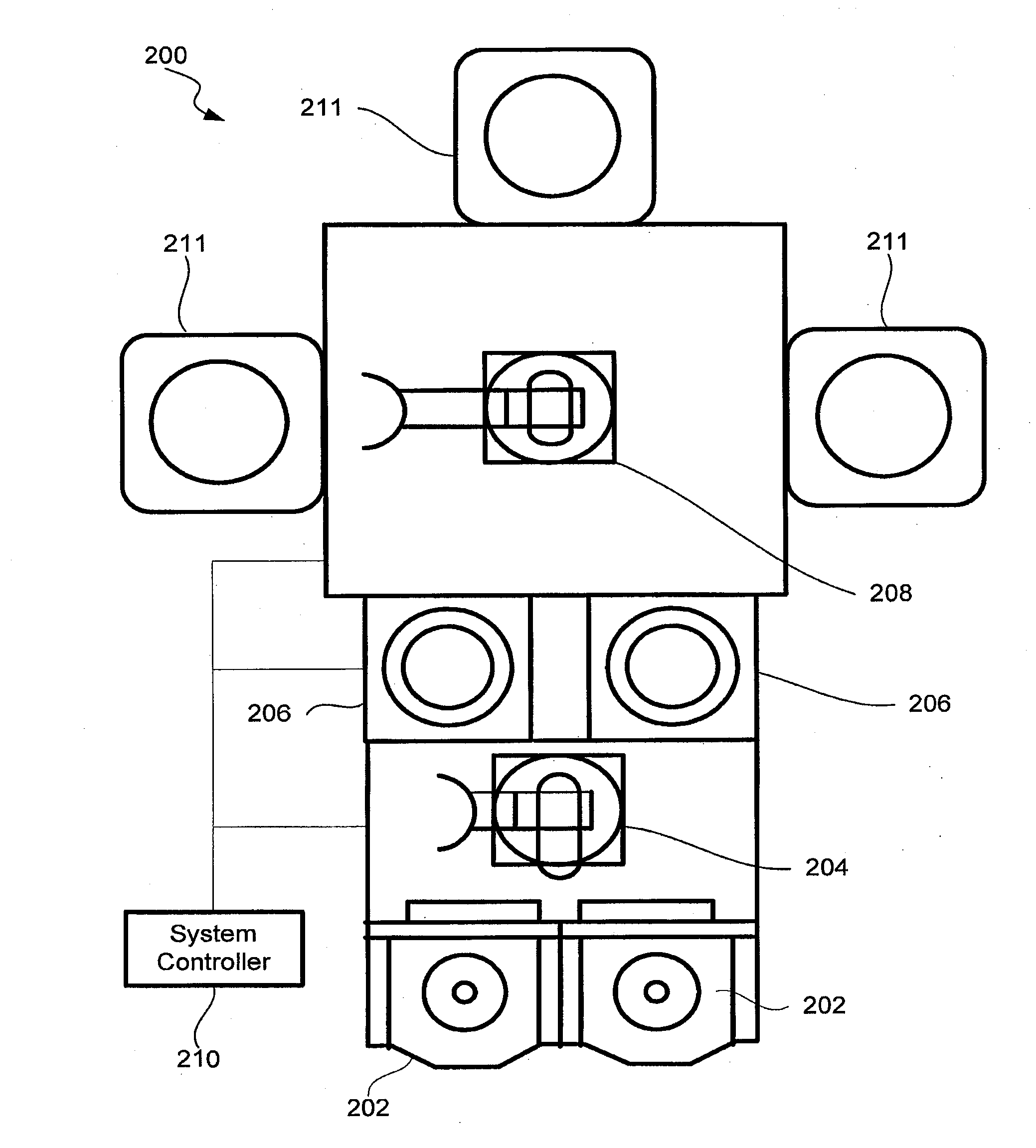
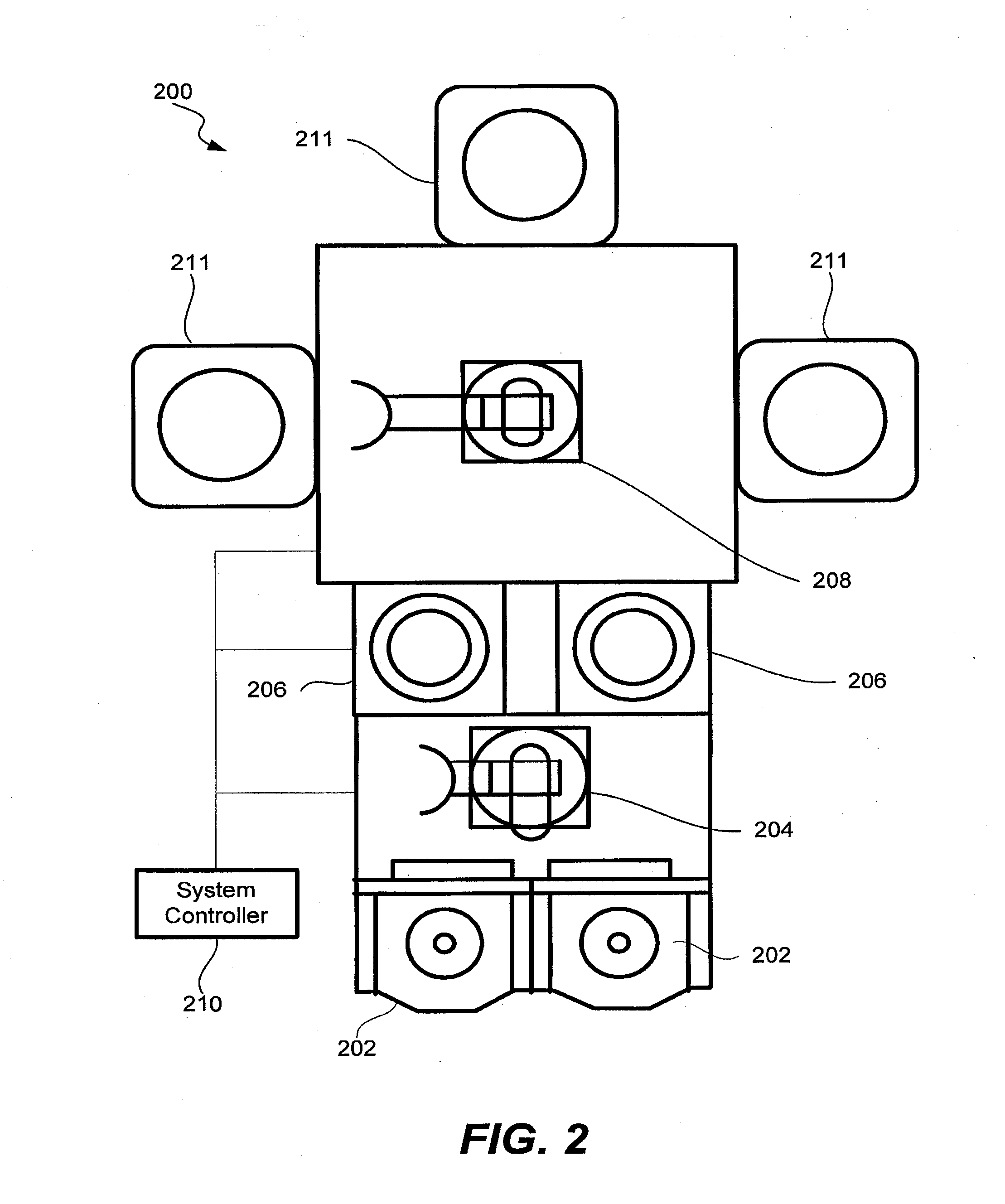
[0026]Load locks are used to transfer wafers between environments at two different pressure levels. Load locks are also often used to cool wafers when transferring them from a low pressure processing side to an atmospheric pressure storage side. For the purposes of this description, “low pressure” and “high pressure” are terms applying to many different pressure regimes. In general they represent two different pressures, usually in the cont...


PUM


Abstract

Apparatuses and methods for cooling and transferring wafers from low pressure environment to high pressure environment are provided. An apparatus may include a cooling pedestal and a set of supports for holding the wafer above the cooling pedestal. The average gap between the wafer and the cooling pedestal may be no greater than about 0.010 inches. Venting gases may be used to increase the pressure inside the apparatus during the transfer. In certain embodiment, venting gases comprise nitrogen.

Description

CROSS REFERENCE TO RELATED APPLICATION[0001]This application is a continuation of prior application Ser. No. 12 / 333,239 filed on Dec. 11, 2008, now pending, the disclosure of which is incorporated by reference herein in its entirety.FIELD OF THE INVENTION[0002]The present invention relates generally to methods and apparatus for transferring wafers using load locks and more particularly to methods and apparatus for cooling wafers while being transferred between lower pressure and higher pressure environments.BACKGROUND OF THE INVENTION[0003]Many semiconductor manufacturing operations are performed at low pressures and high temperatures. Processing modules are often kept at low pressures while wafers are transferred between low and high pressure environments using load locks. Load locks effectively isolate two environments and eliminate the need for repeatedly cycling processing modules, which typically have large internal volumes, between different pressure levels. Instead, only smal...

Claims


Application Information

Patent Timeline
Patent Type & Authority Applications(United States)
IPC IPC(8): H01L21/677
CPCH01L21/67109H01L21/67201Y10S414/135H01L21/6875H01L21/68735
Inventor GAGE, CHRISTOPHERPOMEROY, CHARLES E.COHEN, DAVIDKALYANASUNDARAM, NAGARAJAN
Owner NOVELLUS SYSTEMS
Why Eureka
Try Eureka