Gas compressor and method for controlling flow rate thereof

a gas compressor and flow rate technology, applied in the direction of positive displacement liquid engines, vessel construction, marine propulsion, etc., can solve the problems of significant deterioration of compressor efficiency, stall and surge phenomena, and the inability to fully seal the impeller outlet with the variable diffuser, so as to prevent stall and surge

Inactive Publication Date: 2011-12-29
AIRZEN
View PDF2 Cites 16 Cited by
  • Summary
  • Abstract
  • Description
  • Claims
  • Application Information

AI Technical Summary

Benefits of technology

[0010]The present invention has been made in an effort to provide a gas compressor and a method for controlling a flow rate of the gas c

Problems solved by technology

Therefore, a counter current is generated in the diffuser passage, and as a result, stall and surge phenomena appear.
Moreover, when the flow rate of gas is further reduced or the pressures at the inlet and the outlet of the impeller are the same as each other, a surge mode in which a complete counter current is periodically generated in the diffuser passage starts to thereby significantly deteriorate compressor efficiency.
However, the impeller outlet

Method used


Image

  • Gas compressor and method for controlling flow rate thereof
  • Gas compressor and method for controlling flow rate thereof
  • Gas compressor and method for controlling flow rate thereof

Examples


Embodiment Construction

[0056]The present invention will be described more fully hereinafter with reference to the accompanying drawings, in which exemplary embodiments of the invention are shown. As those skilled in the art would realize, the described embodiments may be modified in various different ways, all without departing from the spirit or scope of the present invention.

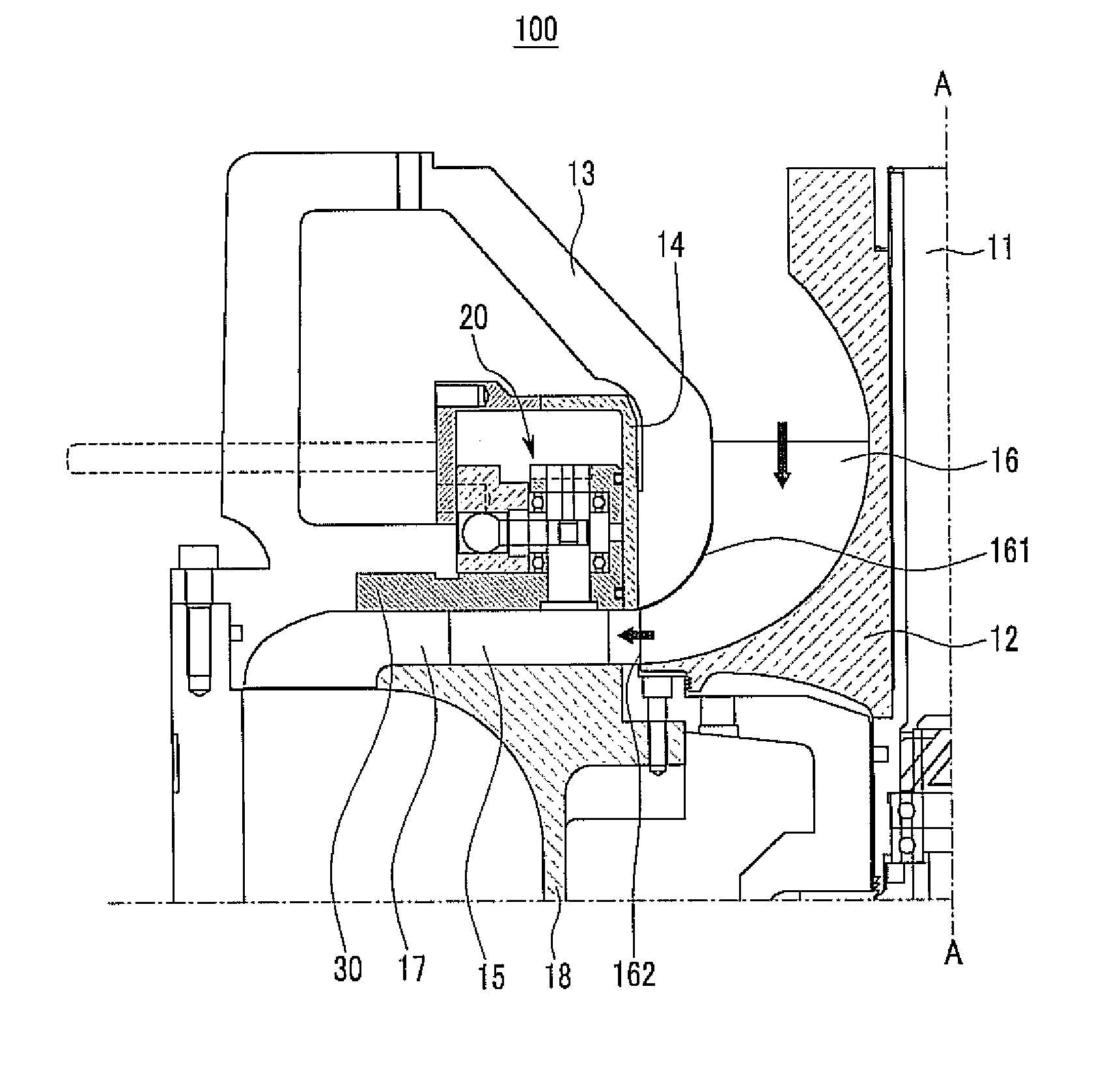
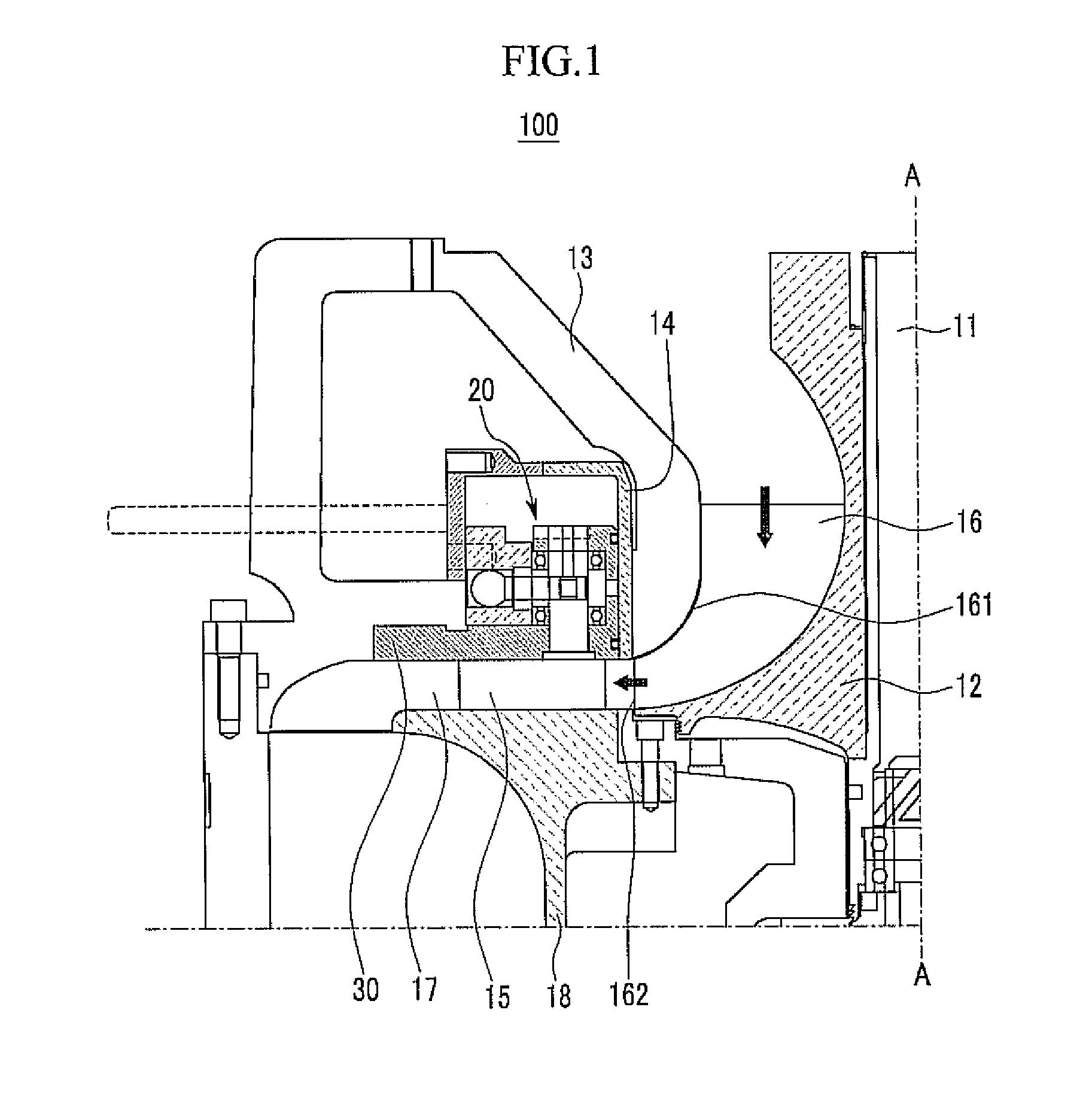
[0057]FIG. 1 is a partial cross-sectional view of a gas compressor 100 according to a first exemplary embodiment of the present invention.

[0058]Referring to FIG. 1, the gas compressor 100 of the first exemplary embodiment includes a rotation shaft 11, an impeller 12, a shroud 13, a ring valve 14, a plurality of veins 15 (one vein is shown in FIG. 1), and an actuator 20. The gas compressor 100 shown in FIG. 1 has bilateral symmetry around a center line (A-A line) of the rotation shaft 11.

[0059]The impeller 12 is fixed to the rotation shaft 11 and the rotation shaft 11 is coupled to a rotation shaft of a motor (not shown). A plurality...


PUM


Abstract

Provided is a gas compressor with a variable diffuser system capable of suppressing stall and surge. The gas compressor includes i) an impeller fixed to a rotation shaft and having a plurality of blades each including a wing surface and an edge surface on an outer circumferential surface thereof; ii) a shroud surrounding the wing surface; iii) a ring valve installed on a diffuser passage connected with an outlet of the impeller and moving in a direction parallel to the rotation shaft to open and close the diffuser passage; iv) a plurality of veins installed in a circumferential direction of the diffuser passage outside the ring valve in the diffuser passage; and v) an actuator coupled with the ring valve and the plurality of veins to sequentially control movement of the ring valve and rotational angles of the veins.

Description

CROSS-REFERENCE TO RELATED APPLICATION[0001]This application claims priority to and the benefit of Korean Patent Application Nos. 10-2009-0019013 and 10-2009-0019011 filed in the Korean Intellectual Property Office on Mar. 5, 2009 and Mar. 5, 2009, the entire contents of which are incorporated herein by reference.BACKGROUND OF THE INVENTION[0002](a) Field of the Invention[0003]The present invention relates to a gas compressor, and more particularly, to a variable diffuser system installed on a diffuser passage connected with an impeller outlet to prevent stall and surge, and a method for controlling a flow rate of the gas compressor using the same.[0004](b) Description of the Related Art[0005]In general, a gas compressor accelerates and compresses gas with a centrifugal compression force of an impeller by passing the gas through the impeller that is rotating. A diffuser passage is connected with an impeller outlet to convert kinetic energy into pressure energy of gas by decelerating...

Claims


Application Information

Patent Timeline
IPC IPC(8): F01D5/22F04B49/06
CPCF04D29/462
Inventor JEONG, KYU-OKJEONG, HYUN-WOOKJEONG, JIN-WOOK
Owner AIRZEN
Why Eureka
Try Eureka