
Carbon nanotube structure

a carbon nanotube and structure technology, applied in the direction of nanostructure assembly, carbon cleaning rags, fibre chemical treatment, etc., can solve the problems of limiting the applications in which carbon nanotubes can be used, particle or powder-shaped carbon nanotubes

Active Publication Date: 2011-12-29
TSINGHUA UNIV +1
View PDF0 Cites 13 Cited by
  • Summary
  • Abstract
  • Description
  • Claims
  • Application Information

AI Technical Summary

Problems solved by technology

The particle or powder-shaped carbon nanotubes limit the applications in which they can be used.

Method used

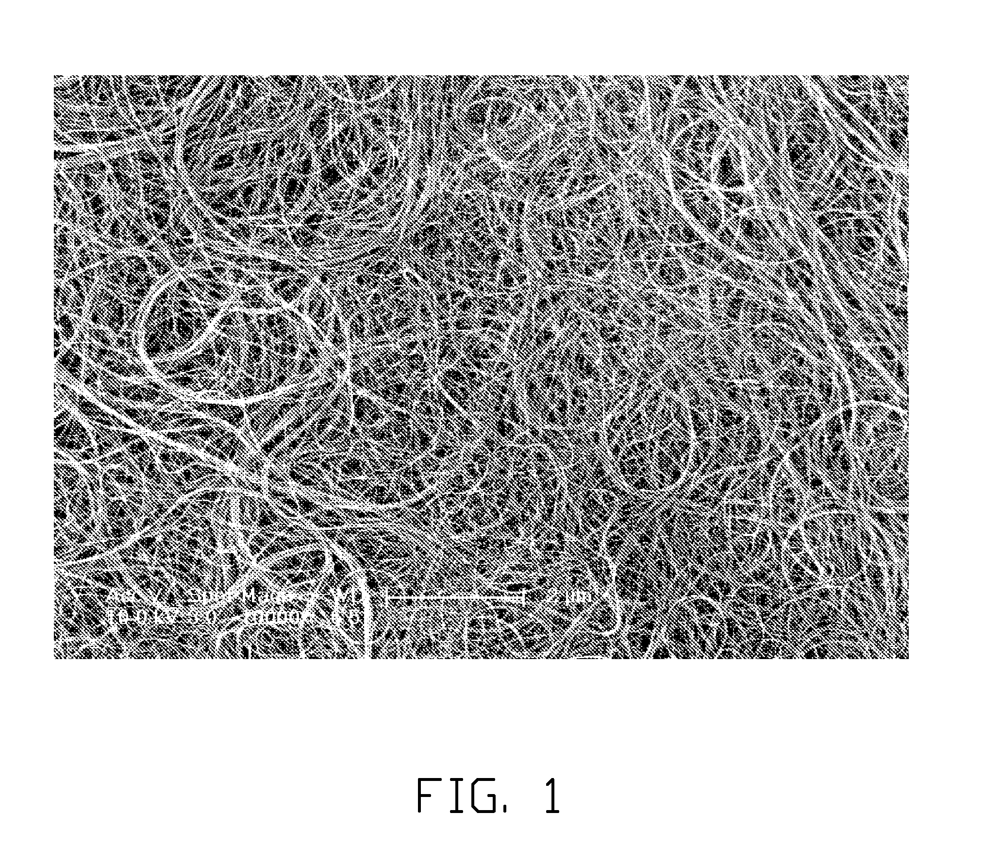
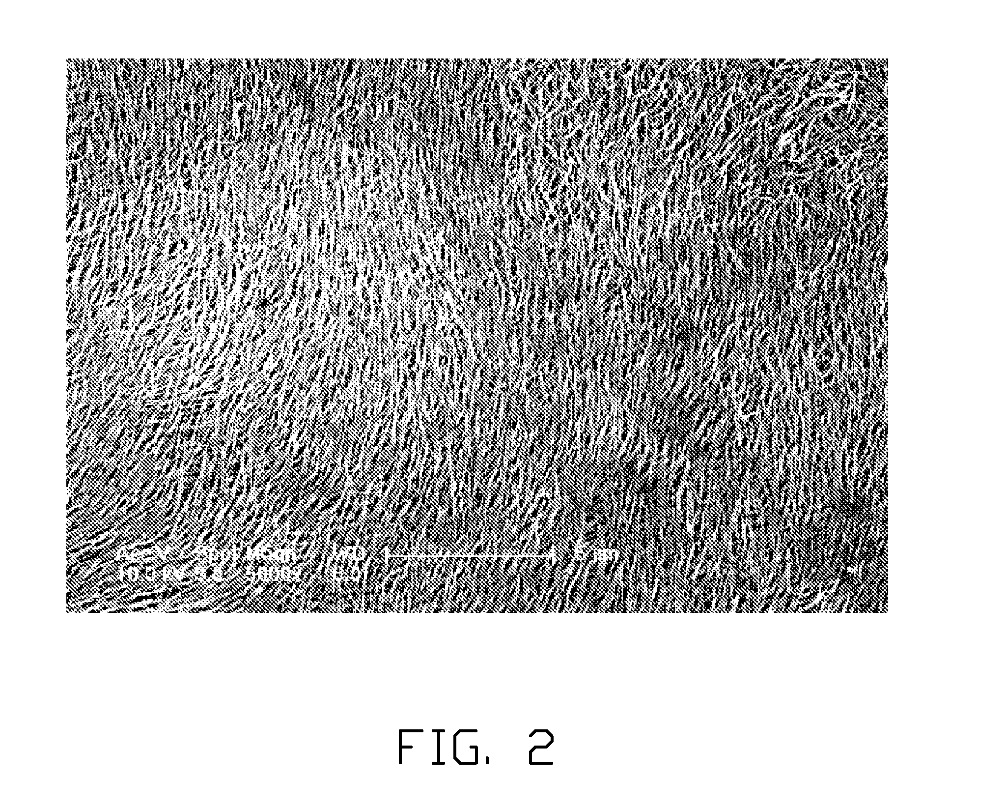
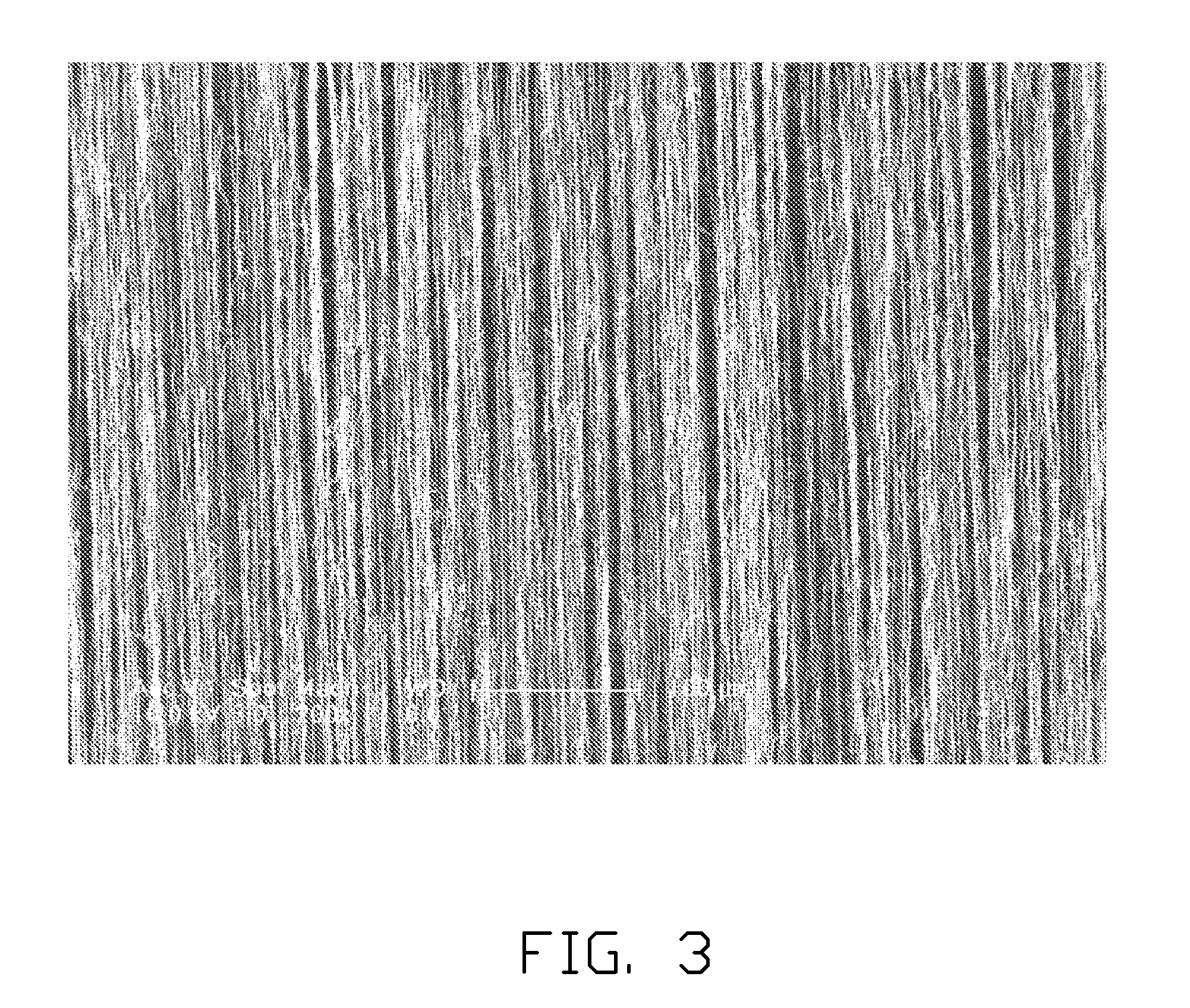

Image

  • Carbon nanotube structure
  • Carbon nanotube structure
  • Carbon nanotube structure

Examples


Embodiment Construction

[0021]The disclosure is illustrated by way of example and not by way of limitation in the figures of the accompanying drawings. It should be noted that references to “an” or “one” embodiment in this disclosure are not necessarily to the same embodiment, and such references mean at least one.

[0022]A method for making a carbon nanotube structure of one embodiment can include the following steps:

[0023]S10, providing a carbon nanotube precursor comprising a plurality of carbon nanotubes joined by van der Waals attractive force therebetween; S20, placing the carbon nanotube precursor in a chamber with low oxygen environment; and

[0024]S30, heating the carbon nanotube precursor in the chamber to form a plurality of carbon-carbon bonds between the carbon nanotubes.

[0025]In step S10, the carbon nanotube precursor can be a planar structure, a linear structure, or other tridimensional structures. The carbon nanotubes distributed in the carbon nanotube precursor can define a plurality of microp...


PUM

PropertyMeasurementUnit
diameteraaaaaaaaaa
sizeaaaaaaaaaa
sizeaaaaaaaaaa

Abstract

A carbon nanotube structure includes a number of carbon wires and a number of second carbon nanotubes. Each of the carbon nanotube wires includes a number of first carbon nanotubes joined end to end by the carbon-carbon bonds therebetween. The carbon wires and the carbon nanotubes are joined by van der Waals attractive force therebetween.

Description

CROSS-REFERENCE TO RELATED APPLICATION[0001]This application claims all benefits accruing under 35 U.S.C. §119 from China Patent Application No. 201010122030.0, filed on Jun. 29, 2010, in the China Intellectual Property Office, the disclosure of which is incorporated herein by reference.[0002]This application is related to a commonly-assigned application entitled, “METHOD FOR MAKING CARBON NANOTUBE STRUCTURE,” filed **** (Atty. Docket No. US33248).BACKGROUND[0003]1. Technical Field[0004]The present disclosure relates to a carbon nanotube structure.[0005]2. Description of Related Art[0006]Carbon nanotubes are tubules of carbon generally having a diameter of about 0.5 nanometers to about 100 nanometers, and composed of a number of coaxial cylinders of graphite sheets. Generally, the carbon nanotubes prepared by conventional methods are in particle or powder forms. The particle or powder-shaped carbon nanotubes limit the applications in which they can be used. Thus, preparation of macr...

Claims


Application Information

Patent Timeline
Patent Type & Authority Applications(United States)
IPC IPC(8): D01F9/12B82Y30/00
CPCB82B3/0047C01B31/022B82Y40/00B82Y30/00C01B32/158C01B32/159
Inventor LIU, KAIJIANG, KAI-LISUN, YING-HUIFAN, SHOU-SHAN
Owner TSINGHUA UNIV
Learn More