System, Method and Computer Program for Pattern Based Intelligent Control, Monitoring and Automation

a technology of intelligent control and monitoring, applied in the field of control, monitoring and automation, can solve the problems of difficult to turn this huge volume of data into valuable information, current systems yield very little information on their own, and can be highly complex

Active Publication Date: 2011-12-29
WONG ANDREW +1
View PDF13 Cites 49 Cited by
  • Summary
  • Abstract
  • Description
  • Claims
  • Application Information

AI Technical Summary

Benefits of technology

[0012]The present invention provides a computer-implementable method for pattern-based monitoring, the method characterized by the steps of: (a) collecting signal data from one or more signals defining signal data streams; (b) transforming each of the signal data streams into trends; and (c) discovering, or facilitating the discovery of, by one or more computer processors, patterns based on the trends within signal data stream and/or across the signal data streams.
[0013]The pre...

Problems solved by technology

However, a manufacturing process can be highly complex.
However, it is very challenging to turn this huge volume of data into valuable information.
When process engineers or plant managers are challenged to find the root cause of a problem, or look for ways to improve the process, current systems yield very little information on their own.
Reports show “what” has happened, but offer little insight into “why” that happened.
The amount of data that is generated by sensors and the complex interactions that occur between process parameters is overwhelming.
Hence, it is virtually impossible for a human, who by nature can only comprehend a problem in several dimensions, to effectively analyze such a complex multivariate problem.
Hence, neural network cannot be used for decision supports.
It has been used in automatic control with limited success.
The major problem is that it is easy for a neural network to overfit the data (i.e. memorize the noises in the system) and yet the operators still do not know the problem.
In practice, it is very difficult for a operator to determine whether the results ge...

Method used


Image

  • System,  Method and Computer Program for Pattern Based Intelligent Control, Monitoring and Automation
  • System,  Method and Computer Program for Pattern Based Intelligent Control, Monitoring and Automation
  • System,  Method and Computer Program for Pattern Based Intelligent Control, Monitoring and Automation

Examples


examples

[0065]The following is provided by example only and is not intended to limit the present invention in any way.

[0066]The invention may be applied to the field of delay coking. Delay coking is one process implemented in oil refineries. Commonly, there may be tens to hundreds of sensors in a delay coking process. Data may be sampled every minute. Over the course of a week, therefore, there may be millions of data points, resulting in a huge data set.

[0067]FIG. 6 illustrates an example of a delay coking apparatus. Sensors linked to the system of the present invention may include pressure, flow speed, temperature, liquid (oil), and manual control sensors of the apparatus. Some sensors, for example, could be oil level of a buffer tank, oil input, oil output, indicator temperature, steam flow, tower temperature, and tower input.

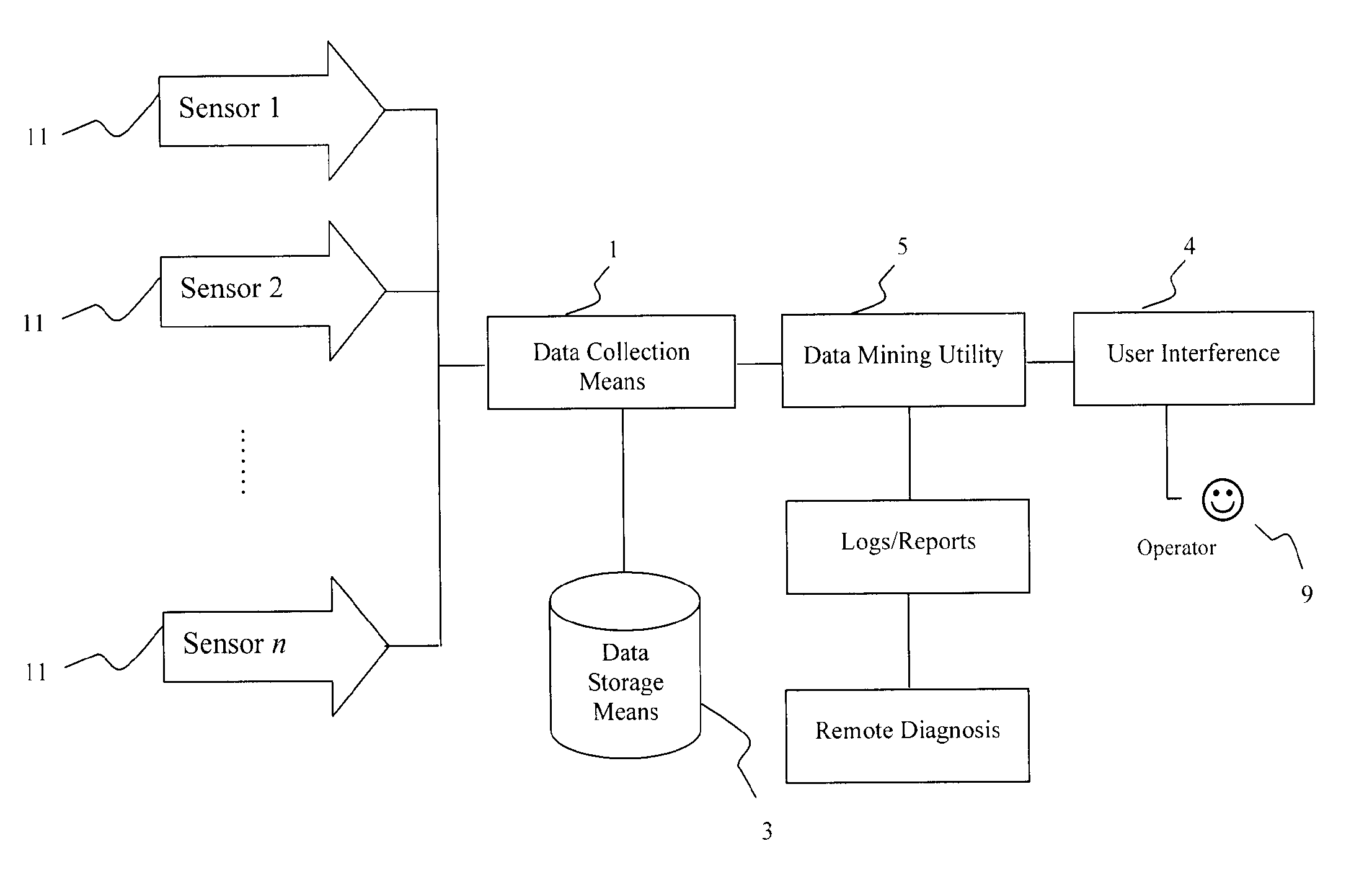
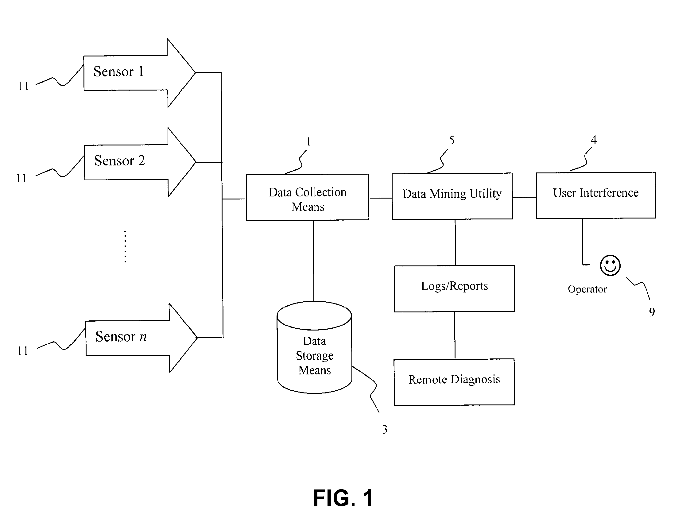
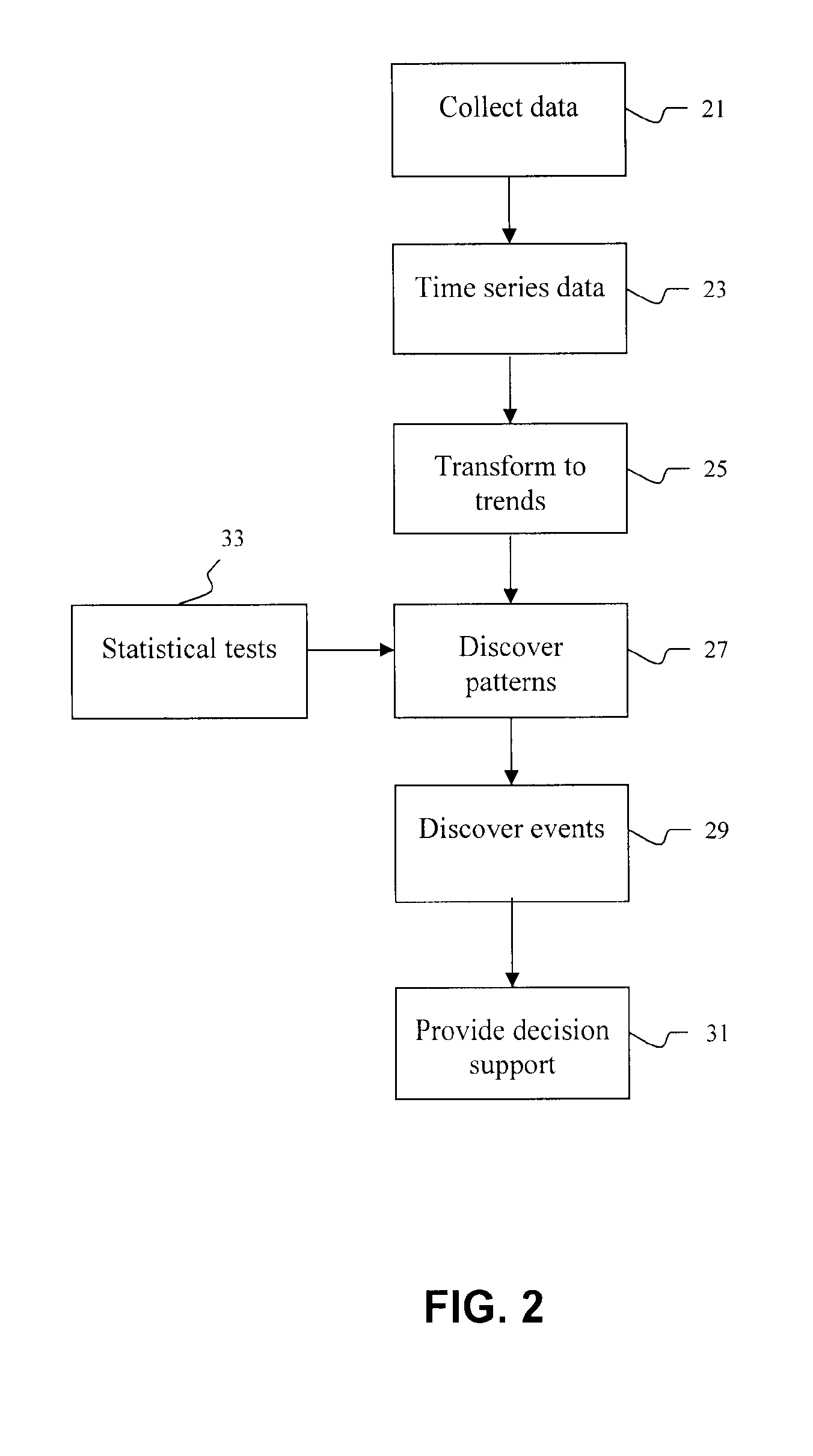
[0068]The system may collect signal data streams from each sensor and transform the signal data streams to trends. Patterns may be discovered from the trends. The u...


PUM


Abstract

The present invention relates to control, monitoring, and automation. The present invention more specifically relates to pattern-based intelligent control, monitoring and automation. The invention performs pattern-based monitoring. It collects signal data from one or more signals. The signal data define signal data streams. It then transforms each of the signal data streams into trends. It also discovers patterns based on the trends within each signal data stream and/or across the signal data streams. The patterns are optionally used for diagnostics and root cause analysis, online plant monitoring and operation control, plant optimization, and other environments where a causal link or correlation may exist between related inputs, states and/or outputs.

Description

FIELD OF THE INVENTION[0001]The present invention relates to control, monitoring and automation. The present invention more specifically relates to pattern-based intelligent control, monitoring and automation.BACKGROUND OF THE INVENTION[0002]Production intelligence is an emerging new field. Production intelligence aims at solving problems including monitoring process operations and alerting operators to an event or alarm; identifying the potential causes of an event; and suggesting possible remedial actions to operators.[0003]Production intelligence can be applied to any field that includes one or more auto-correlated or cross-correlated data. One such field is manufacturing. In manufacturing processes such as oil sand extraction, processing circuits, oil refinery, delay coking, energy and utility, mineral and metal production, power generation, and biofuel / food production, the processes are operated by domain experts (e.g. oil sand plant operators, chemists and geographers) equippe...

Claims


Application Information

Patent Timeline
IPC IPC(8): G06F15/18G06N20/00
CPCG05B23/0278G05B23/0232G06N20/00G06N5/025G06F18/214G06F18/2411G06N7/01
Inventor WONG, ANDREWLI, CHUNG LAM
Owner WONG ANDREW
Why Eureka
Try Eureka