Optical device with lenticular arrays, edge-type backlight module and direct-type backlight module

Active Publication Date: 2012-01-05
ENTIRE TECH CO LTD
View PDF4 Cites 6 Cited by
  • Summary
  • Abstract
  • Description
  • Claims
  • Application Information

AI Technical Summary

Benefits of technology

[0007]The primary objective of present invention is to increase the utilization of light energy of

Problems solved by technology

This is mainly because LCDs release far less radiation than CRT displays, and further due to the significant drops in cost of LCDs in recent years.
In this manner, nearly 10% of light energy from light source is lost and thus cannot be utilized.
Except for the Fresnel loss due to the di

Method used


Image

  • Optical device with lenticular arrays, edge-type backlight module and direct-type backlight module
  • Optical device with lenticular arrays, edge-type backlight module and direct-type backlight module
  • Optical device with lenticular arrays, edge-type backlight module and direct-type backlight module

Examples


Example

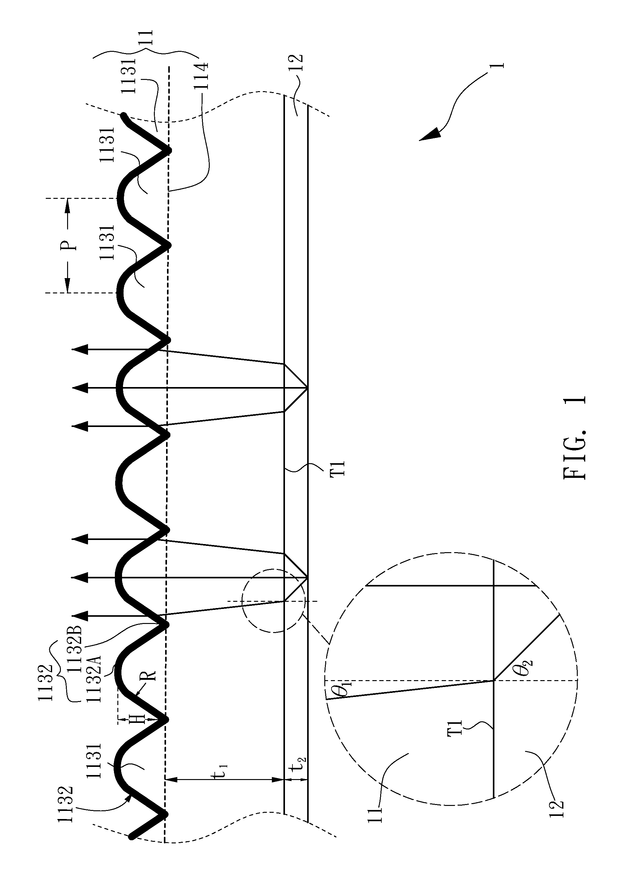
[0031]Please refer now to FIG. 1, FIG. 1 is diagram of the optical device with lenticular arrays according to present invention. An optical device 1 with lenticular arrays comprises an array layer 11 and a second refractive layer 12. The interface T1 is between the array layer 11 and the second refractive layer 12. The array layer 11 includes a base surface 114 and pluralities of lenticular lenses 1131. The lenticular lenses 1131 are disposed and protruded on the base surface 114 side by side. The array layer 11 has a first refractive index n1. A first thickness t1 is the distance between the interface T1 and the base surface 114. Each lenticular lens 1131 contains a curving structure 1132, and the curving structure 1132 includes a peak 1132A, a trough 1132B and has curvature radius (R), width (P) and altitude (H) between the peak 1132A and the trough 1132B; wherein, the trough 1132B is disposed on the base surface 114. The second refractive layer 12 is disposed in the side of incid...


PUM


Abstract

An edge-type backlight module and a direct-type backlight module with a optical device are provided. The optical device comprises an array layer and a second refractive layer. The array layer has a first refractive index (n1) and contains pluralities of lenticular lens disposed on a base surface side by side. The lenticular lens contains a curving structure with a peak, a trough, a curvature radius (R), a width (P) and an altitude (H) between the peak and the trough. The trough is disposed on the base surface. The array layer has a first critical angle (θ1c) relative to the normal of the base surface and satisfies
θ1c=sin-1(1n1)
and
H=R1+K[1-1-(1+K)(P2R)2].
The conical constant (K) of the lenticular lens ranges from −2.1 to −1.5. The second refractive layer is adjacent to the array layer and has a second refractive index (n2) and a second critical angle (θ2c) relative to the normal line of the second refractive layer. The first refractive index (n1) is greater than the second refractive index (n2) and
θ2c=sin-1(n2n1)
is satisfied. Wherein the lenticular lens, the first critical angle (θ1c) and the second critical angle (θ2c) satisfy the equation of
sin-1(1n1)cot-1(HP/2)<sin-1(n2n1).

Description

FIELD OF THE INVENTION[0001]The present invention generally relates to lens arrays, edge-type backlight modules and direct-type backlight modules. More particularly, the present invention relates to an optical device with lenticular arrays that is used thereof in the edge-type backlight module and direct-type backlight module.DESCRIPTION OF THE PRIOR ART[0002]In recent years, traditional Cathode Ray Tube displays (CRT display) has gradually been replaced by Liquid Crystal Displays (LCD). This is mainly because LCDs release far less radiation than CRT displays, and further due to the significant drops in cost of LCDs in recent years. This is why LCDs have come into vogue for utilization in TV or computer display.[0003]In general, an LCD includes a panel and a backlight module. The backlight module may be of two types: a direct-type backlight module or an edge-type backlight module, according to the size of the screen. Both of these two backlight modules may utilize and recycle whole ...

Claims


Application Information

Patent Timeline
IPC IPC(8): F21V7/22G02F1/13357G02B27/12
CPCG02B3/005G02B3/0056G02F2001/133607G02F1/133606G02B6/005G02F1/133607
Inventor LIN, HAO XIANGCHEN, YAN ZUOCHENG, WEN FENGCHANG, JUI HSIANG
Owner ENTIRE TECH CO LTD
Why Eureka
Try Eureka