Wire cutter head for preventing misalignment of the cutting blades

Inactive Publication Date: 2012-01-12
FIST WAY INDAL
View PDF9 Cites 1 Cited by
  • Summary
  • Abstract
  • Description
  • Claims
  • Application Information

AI Technical Summary

Benefits of technology

[0006]An objective of the present invention is to provide a wir

Problems solved by technology

The two blades 711 have a line of contact with each other, and therefore, sometimes slipping may occur due to the small area to which the

Method used


Image

  • Wire cutter head for preventing misalignment of the cutting blades
  • Wire cutter head for preventing misalignment of the cutting blades
  • Wire cutter head for preventing misalignment of the cutting blades

Examples


Example

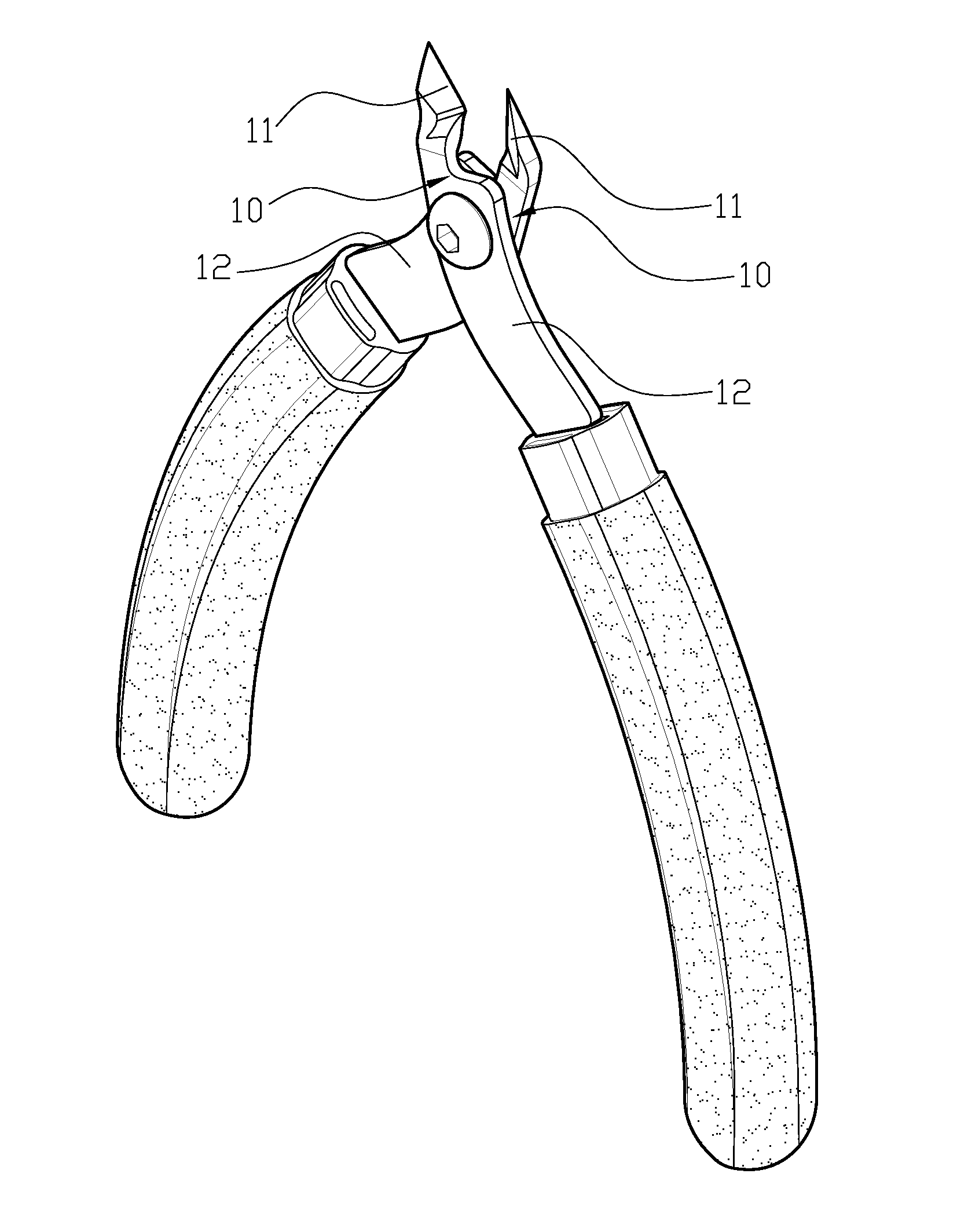
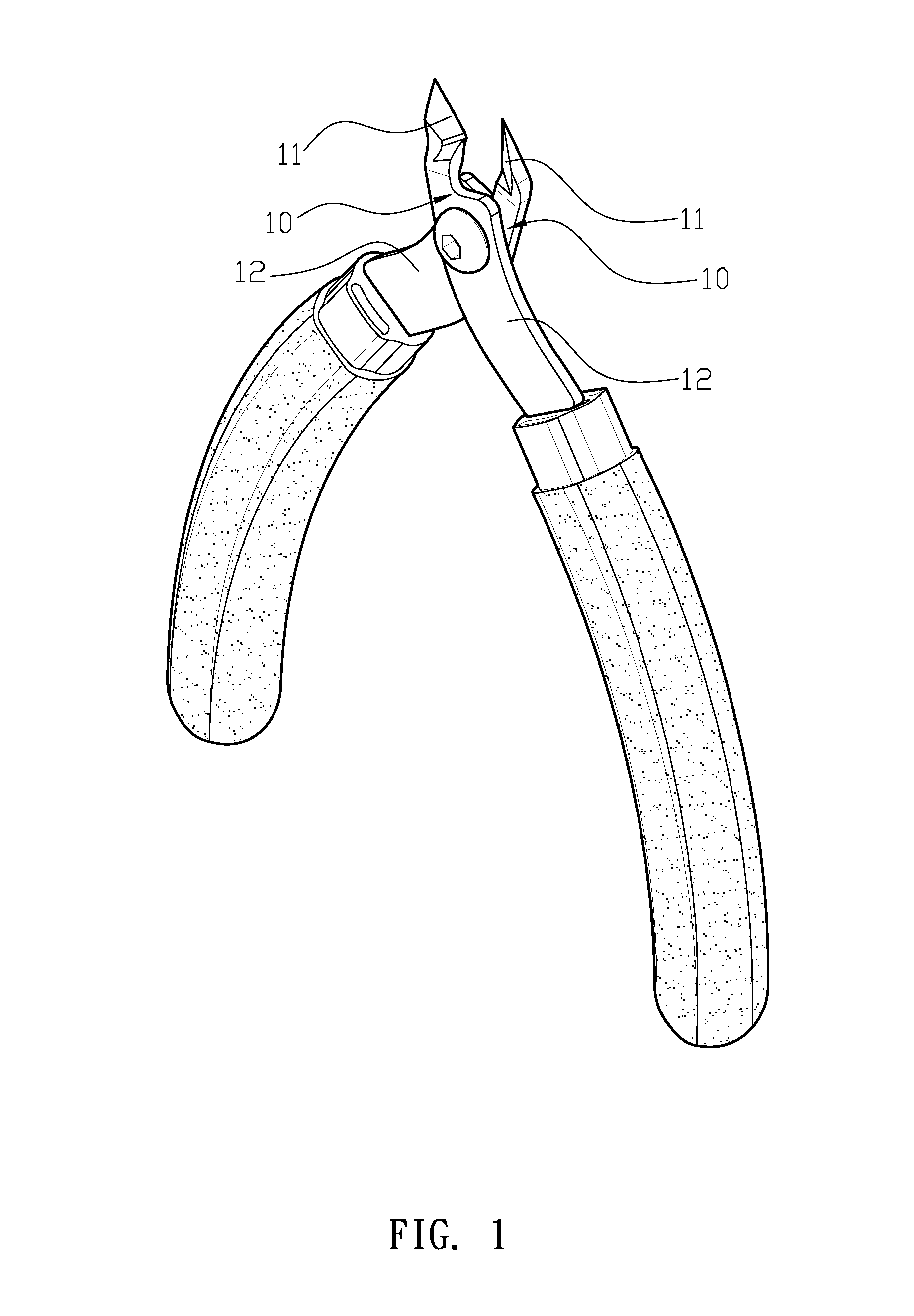
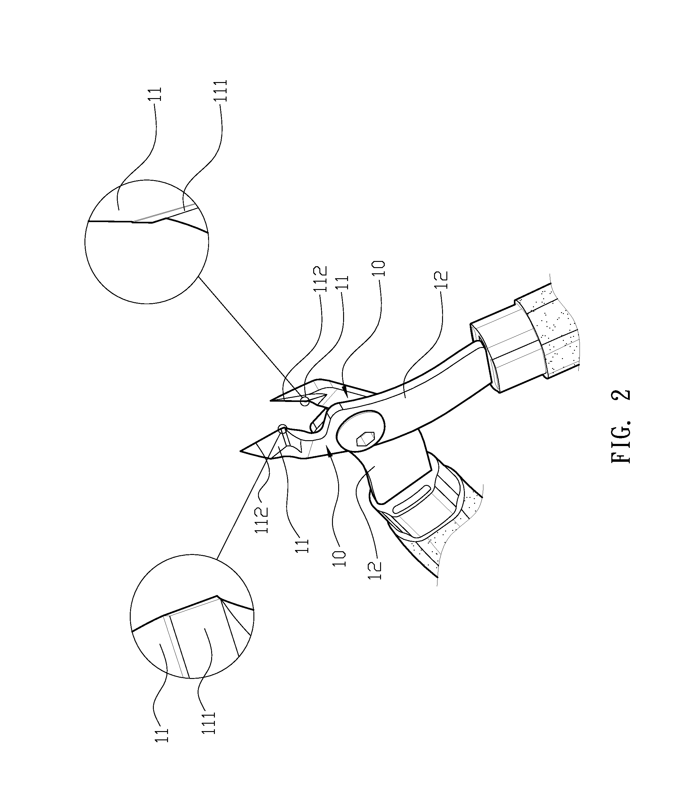
[0018]First, please refer to FIG. 1 and FIG. 2. FIG. 1 is a perspective view of an embodiment of the present invention. FIG. 2 is a local detailed view of a stopping surface and a blade according to an embodiment of the present invention. A wire cutter head for preventing misalignment of cutting blades comprises two cutting members 10; the two cutting members 10 each has a cutting face 11 and a handle neck 12 respectively at two ends and are pivoted together at their middle positions. Each cutting face 11 is a stepped inclined surface having a stopping surface 111 formed with an inclined angle at an approximant middle section, such that the two stopping surfaces 111 are flat, and a blade 112 is formed along a lower edge of the cutting face 11. The handle neck 12 is a plate used for controlling the pivoting angle.

[0019]For assembly, please refer again to FIGS. 1 and 2. The two cutting members 10 are overlapped with each other and pivoted together at the middle section such that the t...


PUM


Abstract

A wire cutter head for preventing misalignment of cutting blades comprises two cutting members, the two cutting members respectively have a cutting face and a handle neck at two ends and are pivoted together at a middle position. The cutting face is a stepped inclined surface having a stopping surface formed with an inclined angle at an approximant middle section, such that the two stopping surfaces are flat with respect to each other, and a blade is formed at a lower edge of the cutting face. The handle neck is a plate used for controlling the pivot angle of the cutting blades. When the handle necks of the cutting members are pressed to rotate the cutting faces, the two facing stopping surfaces and the blades of the two cutting members contact each other. Therefore, the linear contact between the blades is free from misalignment and no offset gap between the blades occurs during operation.

Description

BACKGROUND OF THE INVENTION[0001]1. Field of the Invention[0002]The present invention relates to a wire cutter head for preventing misalignment of the cutting blades, and more particularly to a wire cutter head that is able to prevent misalignment and avoid damage and wearing of the blades.[0003]2. Description of the Related Art[0004]Currently, typical wire cutter heads have the structure as shown in FIGS. 6, 7 and 8, and comprise two cutting members 70. Each cutting member has a cutting face 71 and a handle neck 72 extending from the two respective ends. The two cutting members 70 are pivoted together at a center position, and each cutting face 71 has a blade 711 along an edge. Both of two handle necks 72 are coupled to an elastic member 721 to be forced opened after being pressed together. When the handle necks 72 of the cutting members 70 are placed under stress, the cutting faces rotate to cause the two blades to meet each other to cut objects. The two blades 711 have a line of ...

Claims


Application Information

Patent Timeline
IPC IPC(8): B26B13/00
CPCB26B17/00
Inventor YANG, CHEN-SHENG
Owner FIST WAY INDAL
Why Eureka
Try Eureka