Shell-type radial needle bearing outer ring and method for manufacturing same

A technology for needle roller bearings and manufacturing methods, applied to the outer ring of shell-type radial needle roller bearings and its manufacturing field, capable of solving problems such as increased resistance, increased manufacturing costs, and decreased productivity, so as to prevent positional misalignment and improve fatigue Strength, effect of improving surface properties

Inactive Publication Date: 2012-07-11
NSK LTD
View PDF12 Cites 1 Cited by
  • Summary
  • Abstract
  • Description
  • Claims
  • Application Information

AI Technical Summary

Problems solved by technology

However, if using the Figure 9 Such a structure as shown has the following problems: the shape of the bottom plate portion 9a becomes complicated, the design of the mold used for manufacturing becomes difficult, and the adjustment of the mold becomes troublesome, the productivity decreases, and the manufacturing cost increases.
It is very difficult to find their existence, and if they are kept as they are, there will be problems such as increased resistance when the bearing is press-fitted, and oxide components will be mixed into the inside of the bearing during use.
However, there is a problem that it takes a lot of labor and time to perform individual screening operations for such minute oxides that are difficult to find, and it also costs money.

Method used


Image

  • Shell-type radial needle bearing outer ring and method for manufacturing same
  • Shell-type radial needle bearing outer ring and method for manufacturing same
  • Shell-type radial needle bearing outer ring and method for manufacturing same

Examples


Embodiment

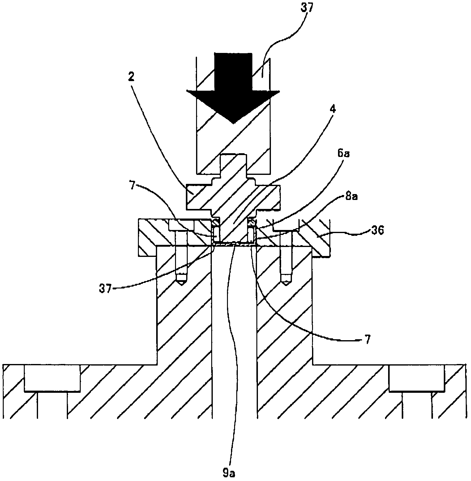
[0069] Experiments performed to confirm the effects of the present invention will be described. In the experiment, as image 3As shown, the cylindrical portion 8a of the outer ring 6a serving as the test piece is fitted and fixed in the holding hole 37 of the fixture 36 with an interference fit. The holding hole 37 is a through hole, and the bottom plate portion 9a of the outer ring 6a is not supported. In this state, the plurality of needle rollers 7 are inserted into the outer ring 6a together with the shaft portion 4 of the cross shaft 2, and the front end surface of the shaft portion 4 is brought into contact with the inner surface of the bottom plate portion 9a. In addition, it was measured that a fluctuating load, which was varied within the range of 500 to 1500 N by the push rod 38, pressed the front end surface of the shaft portion 4 to the inner surface of the bottom plate portion 9a until it was generated on the outer ring 6a as a test piece. The number of times of...


PUM

PropertyMeasurementUnit
sizeaaaaaaaaaa
thicknessaaaaaaaaaa
thicknessaaaaaaaaaa

Abstract

In a shell-type radial needle bearing outer ring (6a) having a cylindrical shape with a bottom, without incurring a cost increase, the bottom plate portion (9a) thereof and the continuous portion between the bottom plate portion (9a) and the cylindrical portion (8a) are improved in fatigue strength, and the anti-rust performance of the outer ring (6a) and the performance for retaining the outer ring (6a) are also improved. After an intermediate material (35) having a cylindrical portion and a bottom plate portion is obtained from a metal material, shot peening is performed on the intermediate material (35) to produce a residual compressive stress in the outer surface side surfaces and surface layer portions of the cylindrical portion (8a) and the bottom plate portion (9a). The residual compressive stress in the outer surface side surface layer portions is made larger than that in the inner surface side surface layer portions and is set to 700 to 1600 MPa in the region from the surfaces to a depth of 0.03 mm.

Description

technical field [0001] The present invention relates to an outer ring constituting a shell-type radial needle roller bearing incorporated into a rotation support portion of a cross-type universal joint called a universal joint, and an improvement in a manufacturing method thereof. Background technique [0002] In order to connect the ends of a pair of rotating shafts that do not exist on the same straight line that constitute the steering device and the transmission shaft of a motor vehicle so that the rotating force (torque) can be transmitted to each other, conventionally, a so-called universal joint shaft is used. Sectional cross shaft universal joint. The cross shaft universal joint such as Image 6 The illustrated figure includes a cross shaft 2 and a pair of yokes 1a and 1b that are fixed to both ends of the above-mentioned rotating shaft and have two branches at their respective front ends. A pair of circular holes 3 concentric with each other are provided at each pa...

Claims


Application Information

Patent Timeline
Patent Type & Authority Applications(China)
IPC IPC(8): F16C33/58F16C19/46F16C33/64F16D3/41
CPCF16C19/466F16C33/64F16C2240/18F16D3/41F16D3/385F16C33/588F16C2220/42B21D53/10F16C21/005F16C2361/41Y10T29/49689B24C1/10B21D53/12F16C2220/40
Inventor 樋口政人竹尾则之小村芳明
Owner NSK LTD
Why Eureka
Try Eureka