Fabrication method for gas-adsorbing device, gas-adsorbing device, and method of using the same

Active Publication Date: 2012-01-12
PANASONIC CORP
View PDF2 Cites 3 Cited by
  • Summary
  • Abstract
  • Description
  • Claims
  • Application Information

AI Technical Summary

Benefits of technology

[0011]The present invention aims at providing a method for fabricating a gas-adsorbing device which is capable of suppressing degradations of a gas-adsorbing member during processing for fabricating the gas-adsorbing device and processing for installing it in a space containing gas to be absorbed thereby and, also, capable of reducing the fabrication costs.
[0013]With the aforementioned structure, the sealing member is preliminarily installed near the opening portion, which enables melting the sealing member, even under conditions where it is hard to perform operations thereon from outside and it is hard to install a movable portion due to the high temperature therein, such as inside of a vacuum heating oven. Thereafter, the temperature is reduced, so that the sealing member can be solidified, thereby sealing the opening portion of the low gas-permeable container. Further, there is no need for employing an additional sealing member, thereby enabling provision of the gas-adsorbing device with lower costs.

Problems solved by technology

For these vacuum apparatuses, residual gasses remaining during fabrication thereof and gasses introduced therein with time cause pressure rises inside thereof, which cause degradations of their performance.
However, with the method described in PLT 1, it is impossible to ensure that the low gas-permeable material covering the gas-adsorbing member has a sufficient gas barrier property.
Therefore, the gas-adsorbing member absorbs ambient gasses during the processing for installing the gas-adsorbing member in the space containing gas to be absorbed thereby, which has made it hard to suppress degradations of the absorption member.
Further, with the method described in PLT 2, there is a need for use of the three members which are inner container 1, outer container 3 and sealing plate 6, thereby involving larger material costs and a larger number of processes.
Therefore, with this method, it has been hard to reduce the costs for the air absorption device.

Method used


Image

  • Fabrication method for gas-adsorbing device, gas-adsorbing device, and method of using the same
  • Fabrication method for gas-adsorbing device, gas-adsorbing device, and method of using the same
  • Fabrication method for gas-adsorbing device, gas-adsorbing device, and method of using the same

Examples


first exemplary embodiment

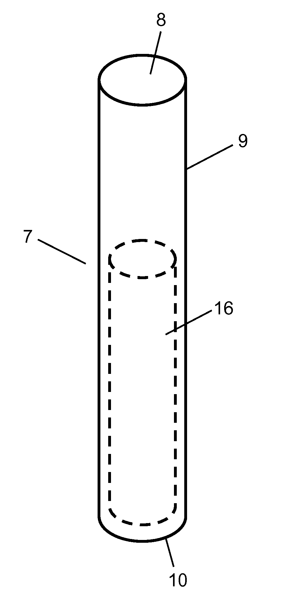
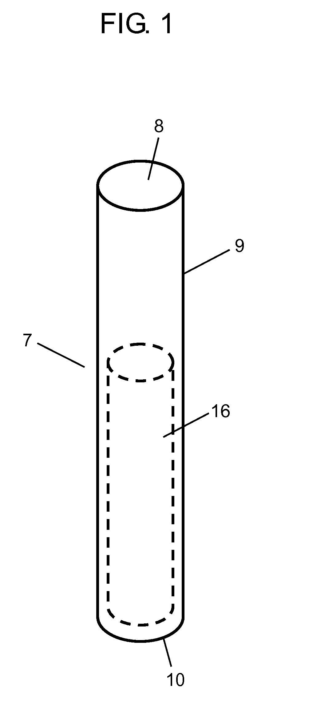
[0048]FIG. 1 is a schematic view of a low gas-permeable container in processing for fabricating a gas-adsorbing device according to a first embodiment of the present invention, before the low gas-permeable container is processed. In FIG. 1, low gas-permeable container 7 comprises a copper having a cylindrical shape with a bottom and, further, has opening portion 8 with a round shape at its one end portion (the upper end). Further, low gas-permeable container 7 has a cylindrical shape having a length of 120 mm and having body portion 9 with a wall thickness of 0.05 mm, and bottom surface 10 with a thickness of 1 mm and an outer diameter of 10 mm. Gas-adsorbing member 16 has been charged in low gas-permeable container 7 through opening portion 8. However, FIGS. 2A and 2B and the figures thereafter will not illustrate gas-adsorbing member 16.

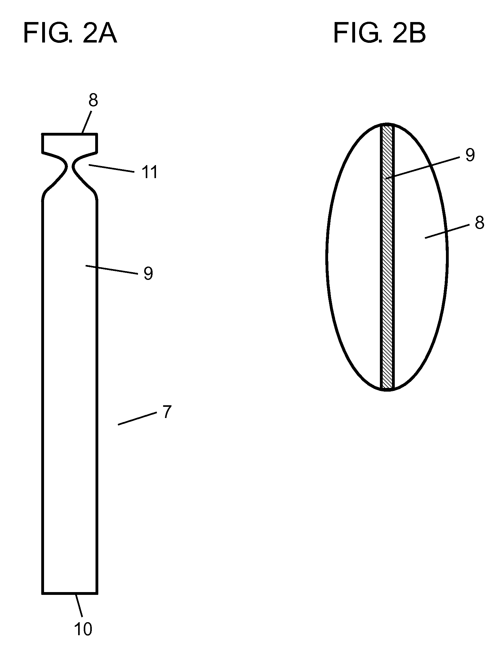
[0049]FIGS. 2A and 2B are schematic views of the low gas-permeable container in the processing for fabricating the gas-adsorbing device, according...

second exemplary embodiment

[0101]FIG. 5 is a schematic view of a low gas-permeable container, in processing for fabricating a gas-adsorbing device according to a second embodiment of the present invention, before the low gas-permeable container is processed. Referring to FIG. 5, low gas-permeable container 7 comprises an iron having a cylindrical shape with a bottom and, further, has opening portion 8 having an elliptical shape with a longer-diameter length of 14 mm and a shorter-diameter length of 6 mm, at its one end portion (the upper end). Further, low gas-permeable container 7 has a length of 120 mm and has body portion 9 with a wall thickness of 0.03 mm, and bottom surface 10 with a thickness of 0.5 mm, wherein body portion 9 has the same cross-sectional shape as that of opening portion 8.

[0102]FIGS. 6A and 6B are schematic views of the low gas-permeable container which has been processed, in the processing for fabricating the gas-adsorbing device, according to the present embodiment. FIG. 6A is a side ...

third exemplary embodiment

[0111]FIG. 9 is a schematic view of a low gas-permeable container, in processing for fabricating a gas-adsorbing device according to a third embodiment of the present invention, before the low gas-permeable container is processed. Referring to FIG. 9, low gas-permeable container 7 comprises an aluminum having an elliptical cylindrical shape with a bottom and, further, has opening portion 8 with an elliptical shape with a longer-diameter length of 14 mm and a shorter-diameter length of 6 mm, at its one end portion (the upper end). Further, low gas-permeable container 7 has a length of 120 mm and has body portion 9 with a wall thickness of 0.2 mm, and bottom surface 10 with a thickness of 0.5 mm, wherein body portion 9 has the same cross-sectional shape as that of opening portion 8.

[0112]FIGS. 10A and 10B are schematic views of the low gas-permeable container which has been processed, in the processing for fabricating the gas-adsorbing device, according to the present embodiment. FIG....


PUM


Abstract

A gas-adsorbing member is charged in low gas-permeable container (7) through its opening portion, wherein low gas-permeable container (7) is constituted by a hollow cylindrical metal member which is opened at its one end and is sealed at its other end and, also, has body portion (9) extending from the one end to the other end thereof such that the length of the body portion is equal to or larger than the maximum width of the end portions. Then, a sealing member is installed within the opening portion and near the opening portion. Then, the sealing member is molten by being heated. Thereafter, the sealing member within the opening portion is cooled to be solidified, thereby attaining sealing of the opening portion. Thus, it is possible to provide a gas-adsorbing-device fabricating method capable of suppressing degradations of the gas-adsorbing member and capable of reducing the fabrication costs.

Description

TECHNICAL FIELD[0001]The present invention relates to fabrication method for gas-adsorbing devices including gas-adsorbing members charged in containers, gas-adsorbing devices, and methods for using gas-adsorbing devices.BACKGROUND ART[0002]In recent years, there have been increasing developments of apparatuses capable of exerting their performance in high-vacuum environments (hereinafter, referred to as vacuum apparatuses), such as vacuum thermal insulation members, vacuum thermal insulation containers, plasma displays.[0003]For these vacuum apparatuses, residual gasses remaining during fabrication thereof and gasses introduced therein with time cause pressure rises inside thereof, which cause degradations of their performance. Therefore, attempts have been made to apply gas-adsorbing members thereto for absorbing such gasses.[0004]If a gas-adsorbing member contacts with air in the atmosphere, the gas-adsorbing member absorbs the air, thereby degrading its gas absorbing ability. Th...

Claims


Application Information

Patent Timeline
IPC IPC(8): B01D53/02B32B1/06B32B38/18
CPCA47J41/028B01D53/0407H01J2211/52F17C3/08H01J9/39F16L59/06F17C11/00B01D39/14
Inventor HASHIDA, MASAMICHI
Owner PANASONIC CORP
Why Eureka
Try Eureka