
Medical sterilization container with gas-exchange filter

Active Publication Date: 2012-01-12
INNOVATIONS MEDICAL
View PDF0 Cites 1 Cited by
  • Summary
  • Abstract
  • Description
  • Claims
  • Application Information

AI Technical Summary

Benefits of technology

[0006]Consequently, a basic object of the present invention is to improve the filter unit of a sterilization container of the type mentioned in the introduction in such a way that the filter sheet is not shifted and / or damage during insertion.
[0008]By means of this embodiment of the filter unit according to the present invention, it is guaranteed with certainty that the filter sheet cannot be shifted or damaged during insertion, since the pressure washer pressing the filter sheet against the wall area does not have to be rotated itself for fixing the pressure washer. Both the spring washer and the pressure washer have at least one smooth surface on their sides facing one another, such that the spring washer can be easily rotated in relation to the pressure washer for establishing the bayonet connection. Thus, the spring washer can, however, be pressed with relatively great prestress against the pressure washer and rotated, without the pressure washer also being moved with it. Thus, the advantage is also further achieved that a higher pressing pressure is exerted onto the pressure washer directly or by means of a sealing ring lying on the filter sheet, as a result of which the sealing action of the sealing ring is improved. Such higher pressing forces are not possible in the previously known filter units, since there the pressure washer has to be rotated to establish the bayonet connection and would lead to destruction of the filter sheet due to the direct frictionally engaged contact of its sealing ring with the filter sheet.
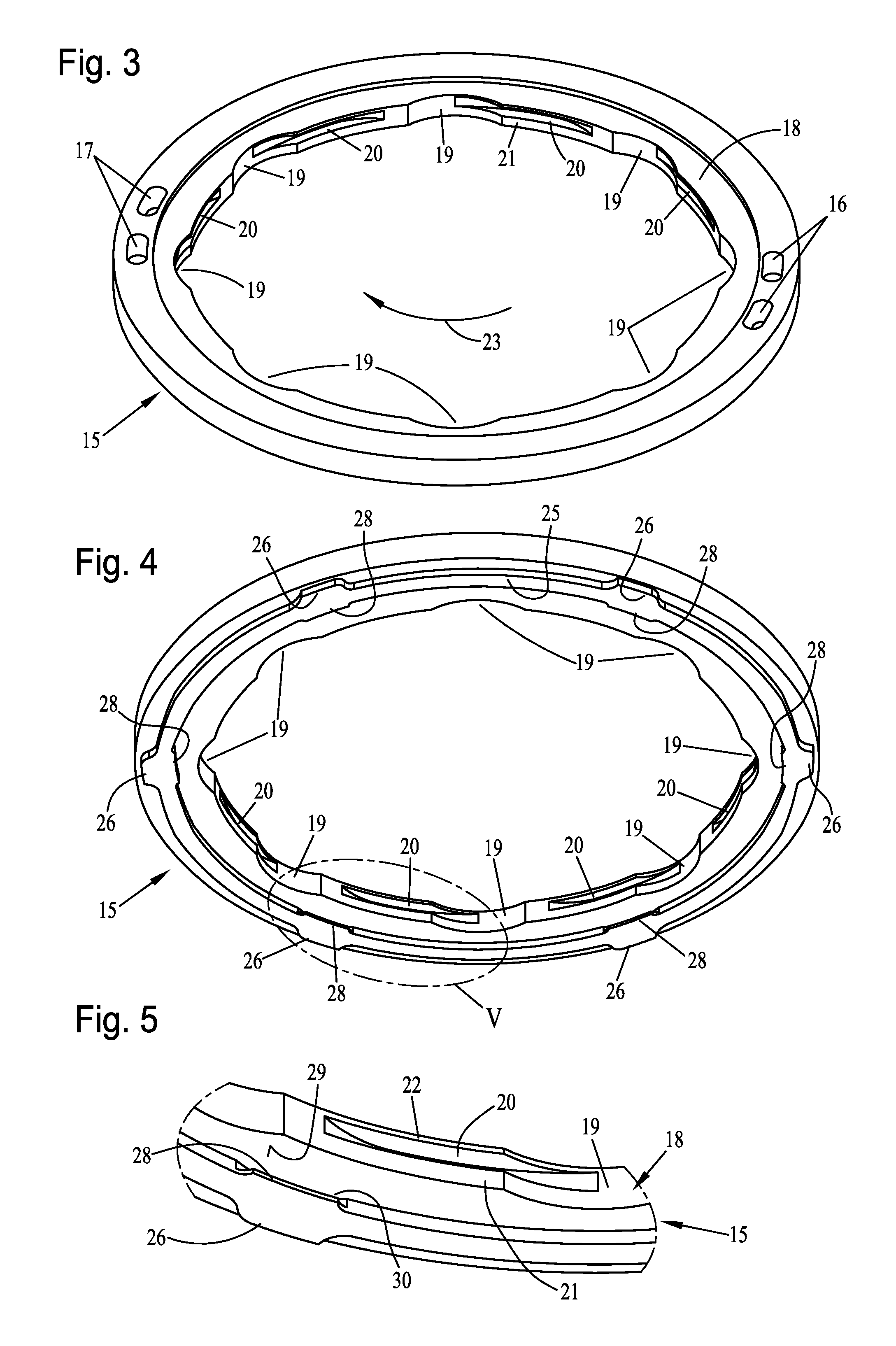
[0010]According to a further aspect of the invention, provisions can be made that the bayonet connection elements of the spring washer are formed from cam- or tongue-like projections protruding radially outwardly on their circular circumference, which mesh with radial mounting slots or grooves arranged on the inside of the frame element, which are each connected to the insertion expansions of the frame element in a direction of rotation. Due to this arrangement and embodiment of the bayonet connection elements, the spring washer can be simply and securely fastened to the frame element of the wall area and be removed again as well, if necessary. Another advantage is that the bayonet connection elements of the spring washer can be produced in a simple and easy manner. Thus, the entire spring washer can be produced in a uniform punching process, in which both the outer contour and the openings can be produced at the same time.
[0012]Further, a further aspect of the invention, provisions may be made that the frame element has a circumferential ring land protruding axially towards the wall area, which ring land meshes with a ring groove of the wall area and is detachably connected to the ring groove via a bayonet connection. By means of this embodiment of the present invention, the frame element can be fastened to the wall area easily and with certainty and can also be removed, if necessary, for example, for cleaning purposes.
[0014]According to a further aspect of the invention, provisions may be made that the spring washer lies axially elastically on the pressure washer in the mounted state and is concentrically rotatably centered on the spring washer by means of a central axial connection. Also by means of this embodiment, the spring washer and the pressure washer can be inserted together into the frame element and can be connected to same in line with the function thereof. By means of the central axial connection, a centering between the pressure washer and the spring washer is achieved, such that these cannot be shifted radially against one another during insertion in or removal from the frame element. Due to the axial, elastic “lying” of the spring washer on the pressure washer, a continuously active spring pressure with a reliable seal is guaranteed, on the one hand, a manual pressing pressure that is too strong is prevented, on the other hand. Thus, too high, harmful pressure forces cannot be exerted onto the pressure washer and thus onto the filter sheet during the insertion of the spring washer.
[0015]Furthermore, provisions may be made according to a further aspect of the invention that the spring washer is provided on its top side with at least one fixed gripping part. By means of this embodiment according to the present invention, the spring washer can be handled in an extremely simple manner. The gripping part here can be arranged centrally on the spring washer. If the common axial connection is also provided, then the spring washer and the pressure washer can be handled via this gripping part together for replacing the filter sheet in an extremely simple manner.

Problems solved by technology

Such higher pressing forces are not possible in the previously known filter units, since there the pressure washer has to be rotated to establish the bayonet connection and would lead to destruction of the filter sheet due to the direct frictionally engaged contact of its sealing ring with the filter sheet.

Method used


Image

  • Medical sterilization container with gas-exchange filter
  • Medical sterilization container with gas-exchange filter
  • Medical sterilization container with gas-exchange filter

Examples


Embodiment Construction

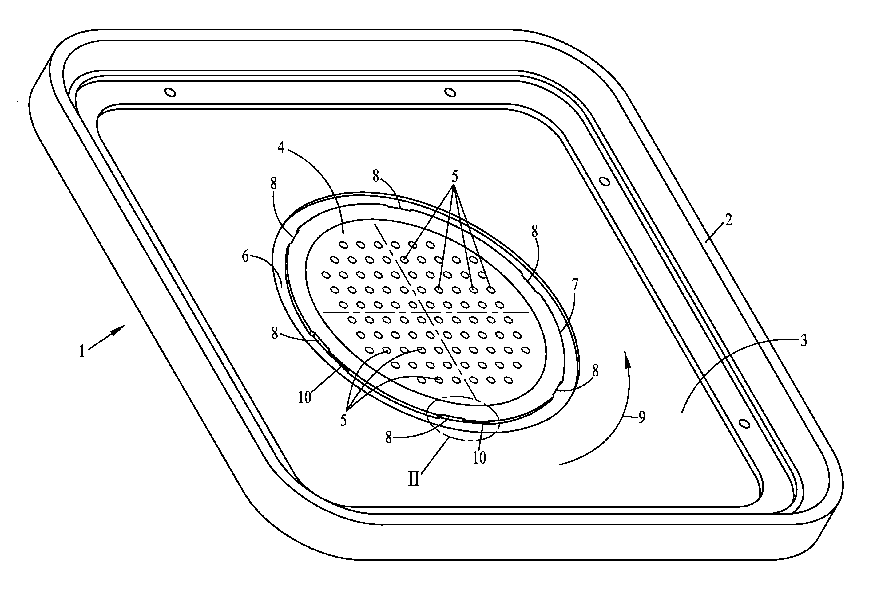
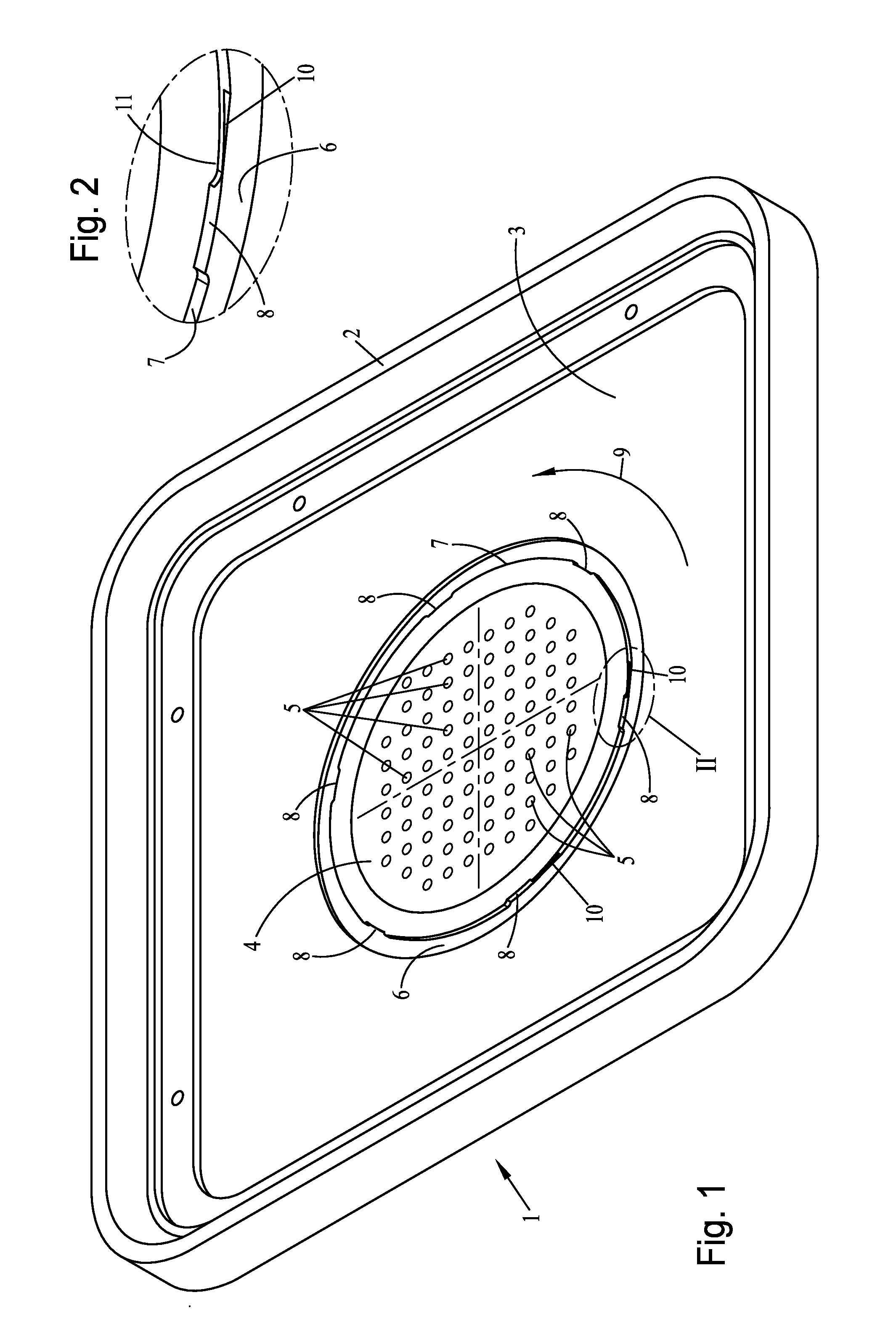
[0033]Referring to the drawings in particular, FIG. 1 shows, in an exemplary manner, an embodiment variant of a container cover 1, which has a rectangular, rounded basic shape. Such a container cover 1 can be placed during operation tightly onto a corresponding container bottom part, which, however, is not shown in the drawing. This container cover 1 forms, with this container bottom part, a medical sterilization container, which is used, for example, to sterilize medical instruments.

[0034]As is evident from FIG. 1, the container cover 1 has a circumferential edge flange 2 that encloses a preferably flat wall element 3 of the container cover 1. Furthermore, a seal is usually provided in the mounted state of the container cover 1 on a container bottom part, such that the container cover 1 can be mounted tightly on the bottom part. Furthermore, it is evident from FIG. 1 that the wall element 3 has a central wall area 4, which in the present exemplary embodiment is provided with a plur...


PUM


Abstract

A medical sterilization container has a removable container cover, which is provided in a wall area (4) with gas-exchange openings (5), with a filter unit (55) for gas exchange has an interchangeable filter sheet covering the gas-exchange openings (5) on the inside, which is arranged within a ring-shaped circumferential frame element (15) and is held pressably against an inside of the wall area (4) by a pressure washer (36) provided with openings (45). The pressure washer (36) is detachably connected to frame element (15) or the wall area (4) and has a ring groove (48) with a preferably elastic sealing ring (49), which seals the wall area (4) provided with the gas-exchange openings (5) against the frame element (15). To prevent a shifting of and / or damage to the filter sheet during a clamping process, the pressure washer (36) can be pressed against the wall area (4) by a spring washer (35). The spring washer (35) is provided with bayonet connection elements (38) which can be meshed and unmeshed with bayonet catch elements (20) of the frame element (15). The spring washer (35) is rotatable opposite the pressure washer (36) about a common central axis of rotation of the pressure washer (36) and of the spring washer (35).

Description

CROSS REFERENCE TO RELATED APPLICATIONS[0001]This application claims the benefit of priority under 35 U.S.C. §119 of German Utility Model Application DE 20 2010 009 925.0 filed Jul. 6, 2010, the entire contents of which are incorporated herein by reference.FIELD OF THE INVENTION[0002]The present invention pertains to a medical sterilization container provided with a removable cover, which is provided in a wall area provided with gas-exchange openings with a filter unit for the gas exchange, which unit has an interchangeable filter sheet covering the gas-exchange openings on the inside, which sheet is arranged within a ring-shaped circumferential frame element and is held pressably against the inside of the wall area by a pressure washer provided with openings, whereby the pressure washer is detachably connected to the frame element or the wall area and has a ring groove with a preferably elastic sealing ring that seals the wall area provided with the gas-exchange openings against th...

Claims


Application Information

Patent Timeline
IPC IPC(8): B08B3/02
CPCA61B19/026A61B2019/0202A61L2202/24A61L2/26A61L2202/182A61B2019/0211A61B2050/0058A61B2050/005A61B50/30
Inventor KREIDLER, WINFRIED
Owner INNOVATIONS MEDICAL
Learn More