
Apparatus and method for lining a pipe junction

a technology for repairing lateral pipes and junctions, which is applied in the direction of pipes/joints/fittings, mechanical equipment, pipe elements, etc., can solve the problems of difficult alignment of lateral liner tubes and lateral pipes, and it is not feasible to position cameras in lateral pipes

Inactive Publication Date: 2012-01-12
LMK TECH LLC
View PDF27 Cites 16 Cited by
  • Summary
  • Abstract
  • Description
  • Claims
  • Application Information

AI Technical Summary

Benefits of technology

[0005]It is therefore a principal object, feature, or advantage of the present invention to provide an improved apparatus and method for repairing the juncture of a main sewer line with a lateral pipe.
[0006]Another object, feature, or advantage of the present invention is to provide an improved method and apparatus for remotely positioning a liner assembly in a main pipe.
[0007]Another object, feature, or advantage of the present invention is to provide an improved method and apparatus for remotely aligning a liner assembly with a lateral pipe.
[0008]These and / or other objects, features, and advantages of the present invention will be apparent to those skilled in the art. The present invention is not to be limited to or by these objects, features and advantages.
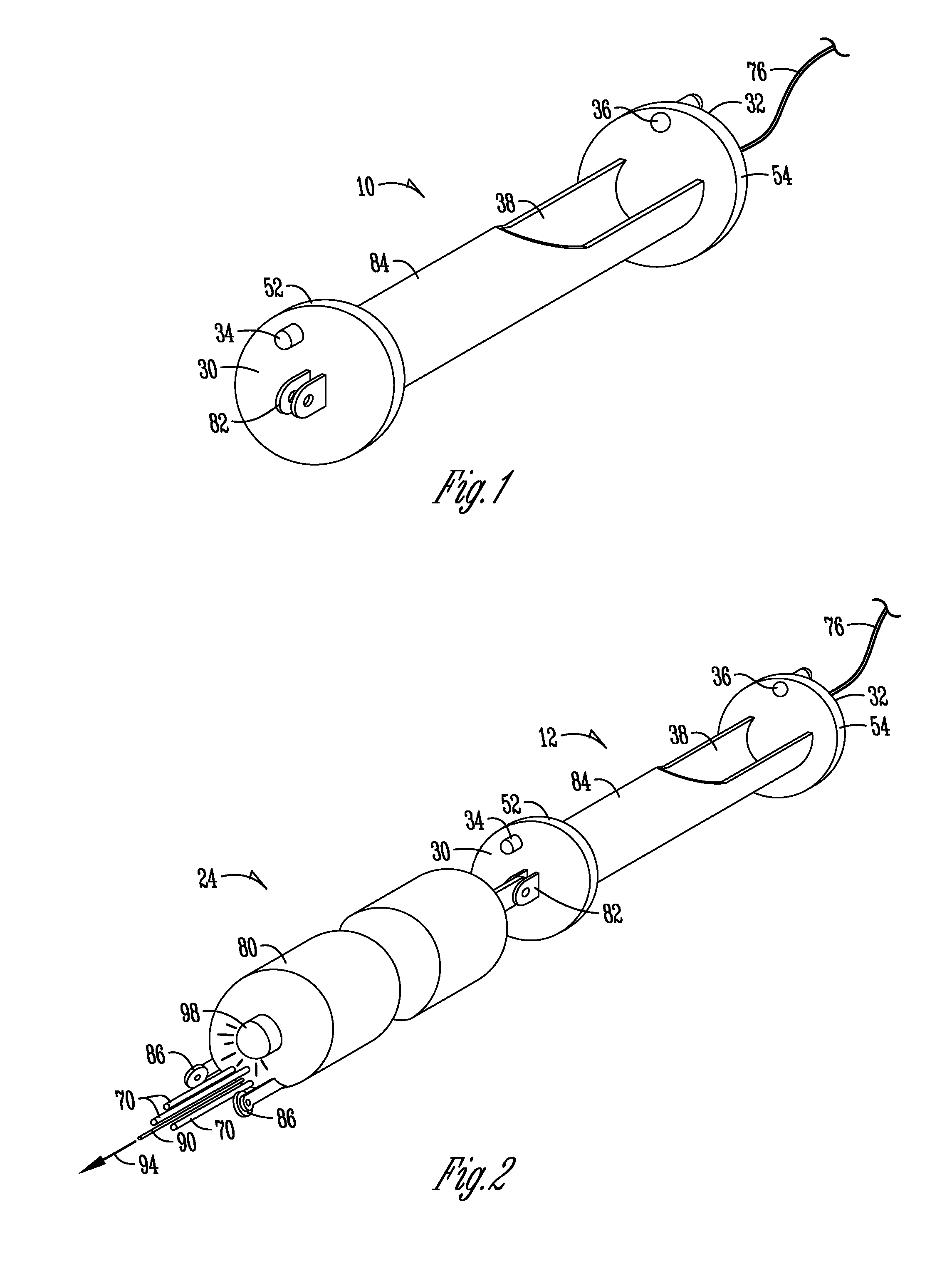
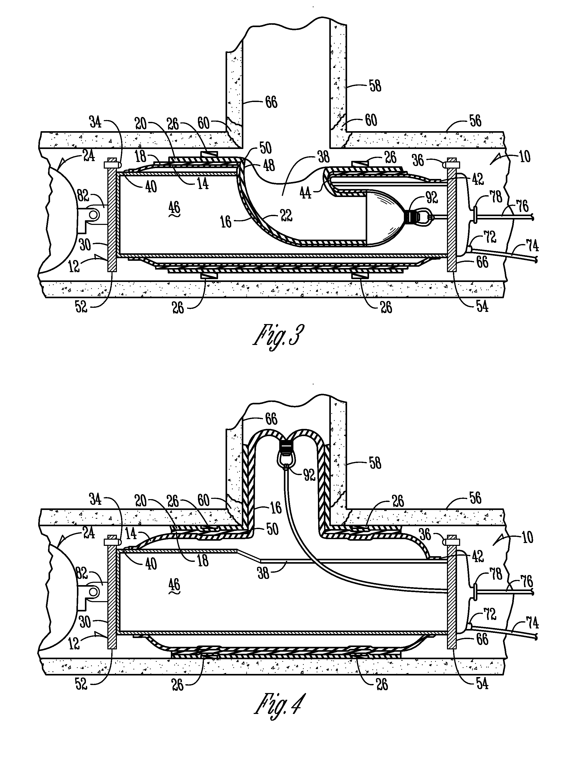
[0009]According to one aspect of the present invention, a liner assembly is provided. The liner assembly includes a launcher device, a main bladder tube, a lateral bladder tube, a containment bladder, a main liner member, and a lateral liner tube. The launcher device includes opposite first and second ends, an opening there between, and first and second cameras operably attached on opposite sides of and oriented towards the opening. The main bladder tube has opposite first and second ends, and a main bladder tube opening there between, and is outside and at least partially surrounds the launcher device. The lateral bladder tube extends from the main bladder tube opening and into the inside of the launcher device. The containment bladder at least partially surrounds the main bladder tube. The main liner member includes a main liner member opening, and at least partially surrounds the containment bladder. The lateral liner tube extends from the main liner member opening and through the main bladder tube opening and into the inside of the lateral bladder tube.
[0010]According to another aspect of the present invention, a method of lining a lateral pipe from a main pipe is provided. The method includes providing a liner assembly including a launcher device having first and second image devices operable attached thereto, a lateral bladder tube, and a lateral liner tube. The liner assembly is positioned in the main pipe. Image data is acquired from the first and second image device. The image data is used to assist in aligning the launcher device opening with the lateral pipe. The main liner member is pressed against the main pipe. The lateral liner tube is inserted into the lateral pipe, and the lateral liner tube is pressed against an interior wall of the lateral pipe.

Problems solved by technology

However, in some instances it is not feasible to position a camera in the lateral pipe.
It is also known to position a camera in the main pipe, but the viewing angles make it difficult to align the lateral liner tube with the lateral pipe.

Method used


Image

  • Apparatus and method for lining a pipe junction
  • Apparatus and method for lining a pipe junction
  • Apparatus and method for lining a pipe junction

Examples


Embodiment Construction

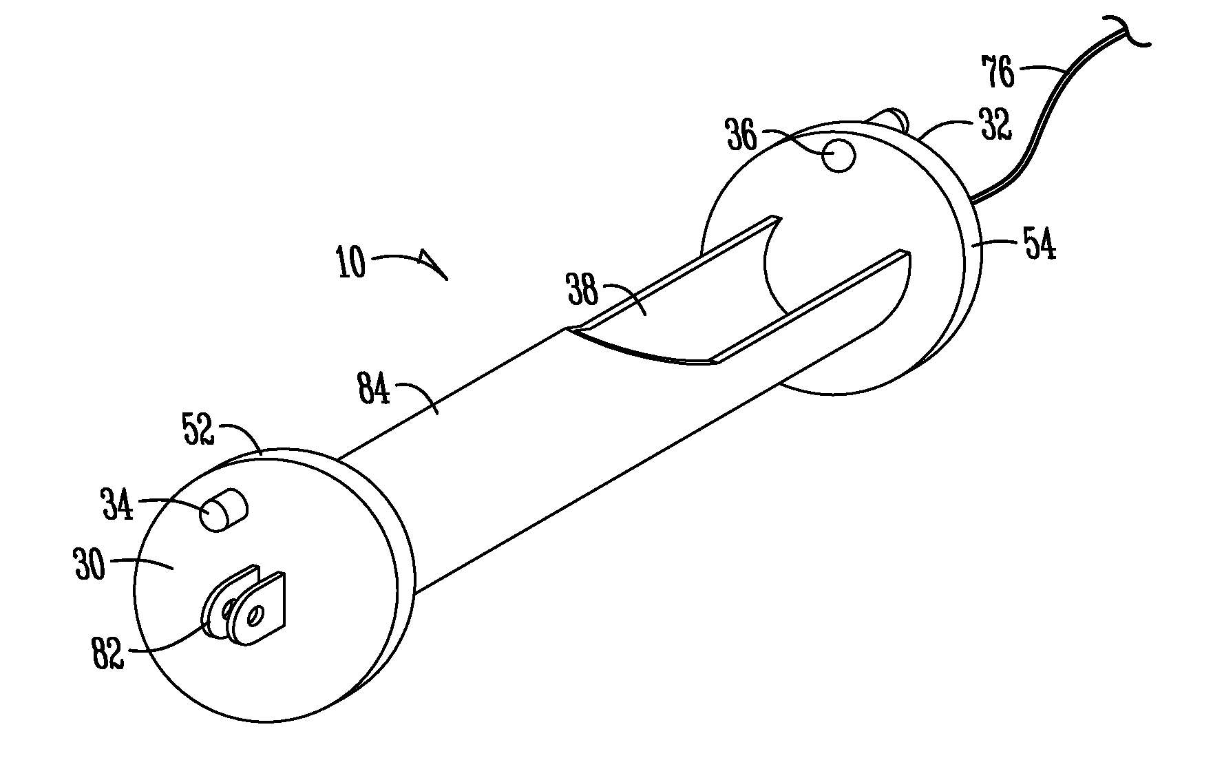
[0034]Referring to FIGS. 3-5, a liner assembly is generally designated by the numeral 10. The liner assembly 10 includes a launcher device 12 having mounted thereto a T-shaped or Y-shaped liner and bladder. The liner consists of a main liner member 20 and a lateral liner tube 22. In one embodiment, the main liner member 20 is a tube, but it may also be other shapes as well, such as a collar. The bladder consists of a main bladder tube 14, comprising a first end 40, a second end 42, a main bladder tube opening 44, and a lateral bladder tube 16. The liner assembly 10 may also consist of a containment bladder 18, as well as hydrophilic seals 26. In the particular configuration shown in FIGS. 3-5, the liner and bladder are T-shaped, but they can also be Y-shaped to accommodate the lateral pipeline that intersects with a main pipeline at an oblique angle.

[0035]Now referring to FIG. 1, a launcher device 12 will be discussed in more detail. The launcher device 12 includes a first skid 52 o...


PUM


Abstract

A liner assembly is provided for repairing a pipe junction. The liner assembly includes a first and second camera and a containment bladder all operably connected to a launcher device, and which are used in combination by a user in a remote location to position and align the liner assembly in a main pipe, adjacent a lateral pipe, wherein no external access to the lateral pipe is available. The user will use images from the cameras to send control information to a positioning device, which positions and aligns a liner assembly with a lateral pipe. The liner assembly is then used to repair damage to the lateral pipe and the juncture between the main and lateral pipes.

Description

FIELD OF THE INVENTION[0001]The present invention relates generally to sewer pipe line repair, and more particularly to an improved method and apparatus for repairing a lateral pipe of a sewer.BACKGROUND OF THE INVENTION[0002]It is known in the art to install a main and lateral sewer pipe repair assembly from a main pipe. The assembly is moved through a main pipe until it reaches its destination, usually a position adjacent a lateral pipe. A lateral liner tube, which has been impregnated with a thermoset resinous material, is inverted from the assembly into the lateral pipe by inflating a lateral bladder tube. At the same time, a main bladder tube is inflated, which presses a main liner member against an area of the main pipe adjacent the lateral pipe opening to repair the juncture of the main and lateral pipe. Once the resin has cured, the bladders are removed from the lateral and main pipes, and the assembly is removed from the main pipe, while the cured main and lateral liners re...

Claims


Application Information

Patent Timeline
IPC IPC(8): F16L55/16
CPCF16L55/1651F16L55/265F16L55/179
Inventor KIEST, JR., LARRY W.
Owner LMK TECH LLC
Learn More