
High Seal Retractor Pretensioner Piston

a high-sealed, piston technology, applied in the direction of belt retractors, vehicle safety belts, vehicle components, etc., can solve the problems of reducing the pressure and force available for pretensioning seat belts, and efficient utilization, and achieve the effect of reducing gas leakag

Inactive Publication Date: 2012-01-12
AUTOLIV ASP INC
View PDF6 Cites 50 Cited by
  • Summary
  • Abstract
  • Description
  • Claims
  • Application Information

AI Technical Summary

Benefits of technology

[0005]The present invention provides a pretensioner assembly that substantially reduces gas leakages within a pretensioner tube. The pretensioner assembly includes a pretensioner tube in communication with a gas generator. A driving element in the form of a piston having a generally cylindrical outer surface is disposed within the tube. The piston is operable to impart motion onto driving a element such as a plurality of balls loaded in the tube (or a “ball string”) in reaction to pressurized gas discharged from the gas generator. The piston includes a proximate end spaced from the gas generator so as to define a gas chamber therebetween. The piston further includes a distal end facing the plurality of balls. Portions of the proximate end and the distal end are indented inward to form concave depressions at each end.
[0006]The concave depressions include flexible rims that act as pressure-activated seals. More specifically, the flexible rim at the proximate end is configured to expand circumferentially outward in response to forces exerted by the pressurized gas from the gas generator, and the flexible rim at the distal end is configured to expand circumferentially outward due to the application of backpressure from the plurality of balls. The expansion of the flexible rims at the proximate and distal ends create a tight seal between the piston and an inner peripheral wall of the tube, thereby reducing gas leakage beyond the distal end of the piston.

Problems solved by technology

One issue with pretensioners utilizing gas generators is efficient utilization of the gas volume produced by the generator.
For instance, a significant volume of the gas produced by the gas generator can leak through the pretensioner tube or around the piston or balls, thereby decreasing the pressure and force available for pretensioning the seat belt.

Method used


Image

  • High Seal Retractor Pretensioner Piston
  • High Seal Retractor Pretensioner Piston
  • High Seal Retractor Pretensioner Piston

Examples


Embodiment Construction

[0018]The following description is merely exemplary in nature and is not intended to limit the present disclosure or its application or uses.

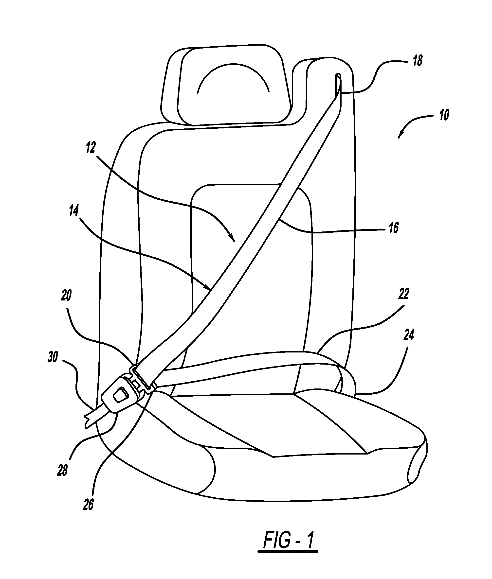
[0019]Referring now to the drawings, FIG. 1 shows a vehicle seat 10 and a seat belt assembly 12. The seat belt assembly 12 includes a seat belt webbing 14 having a shoulder belt portion 16 extending from an upper anchorage 18 to a buckle loop 20 and a lap belt portion 22 extending from the buckle loop 20 to an anchor point 24. A buckle latch plate 26 is able to be inserted into a seat belt buckle 28 to lock and unlock the seat belt assembly 12. A seat belt buckle cable 30, either directly or in cooperation with other components, secures the seat belt buckle 28 to a portion of the vehicle frame.

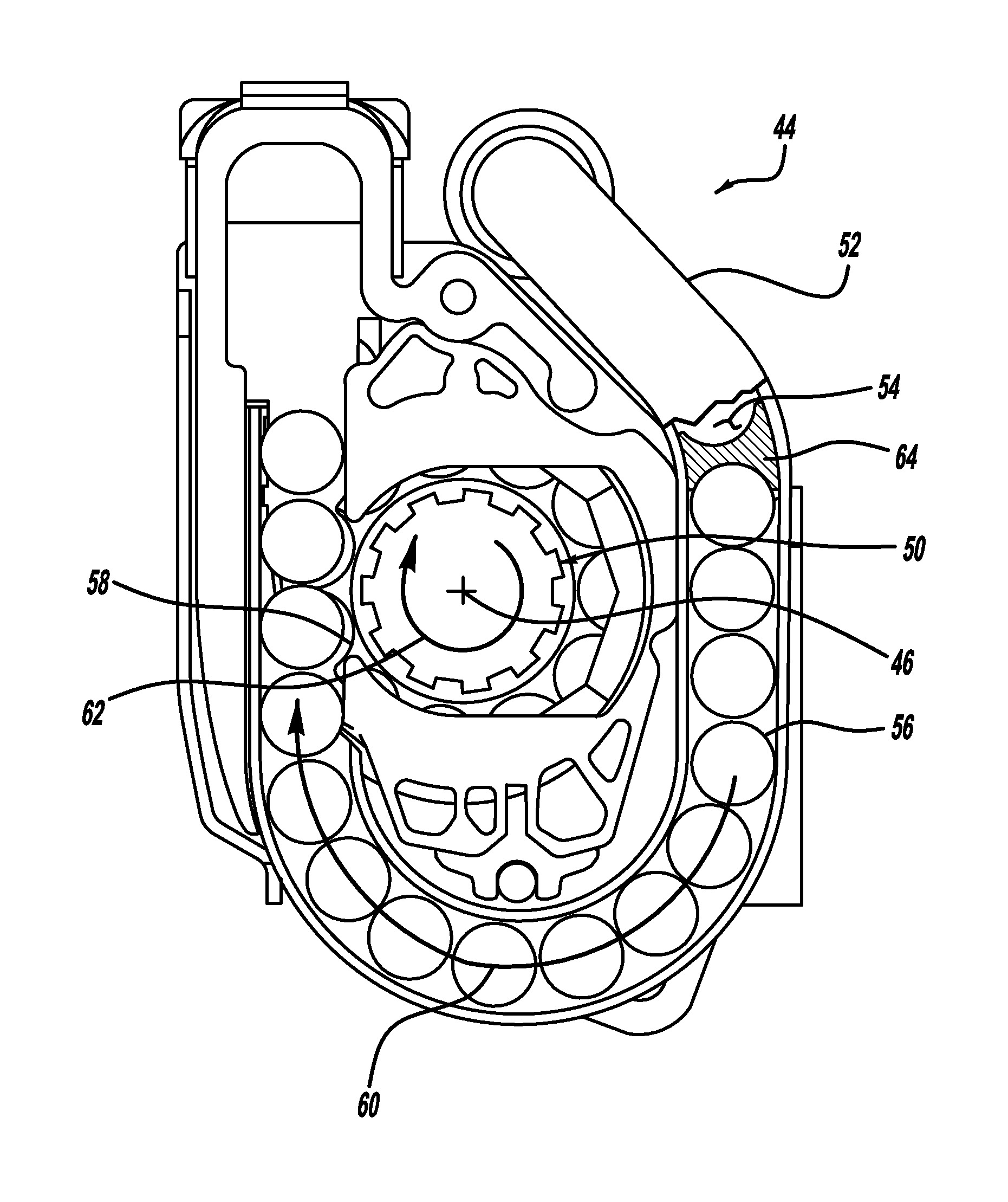
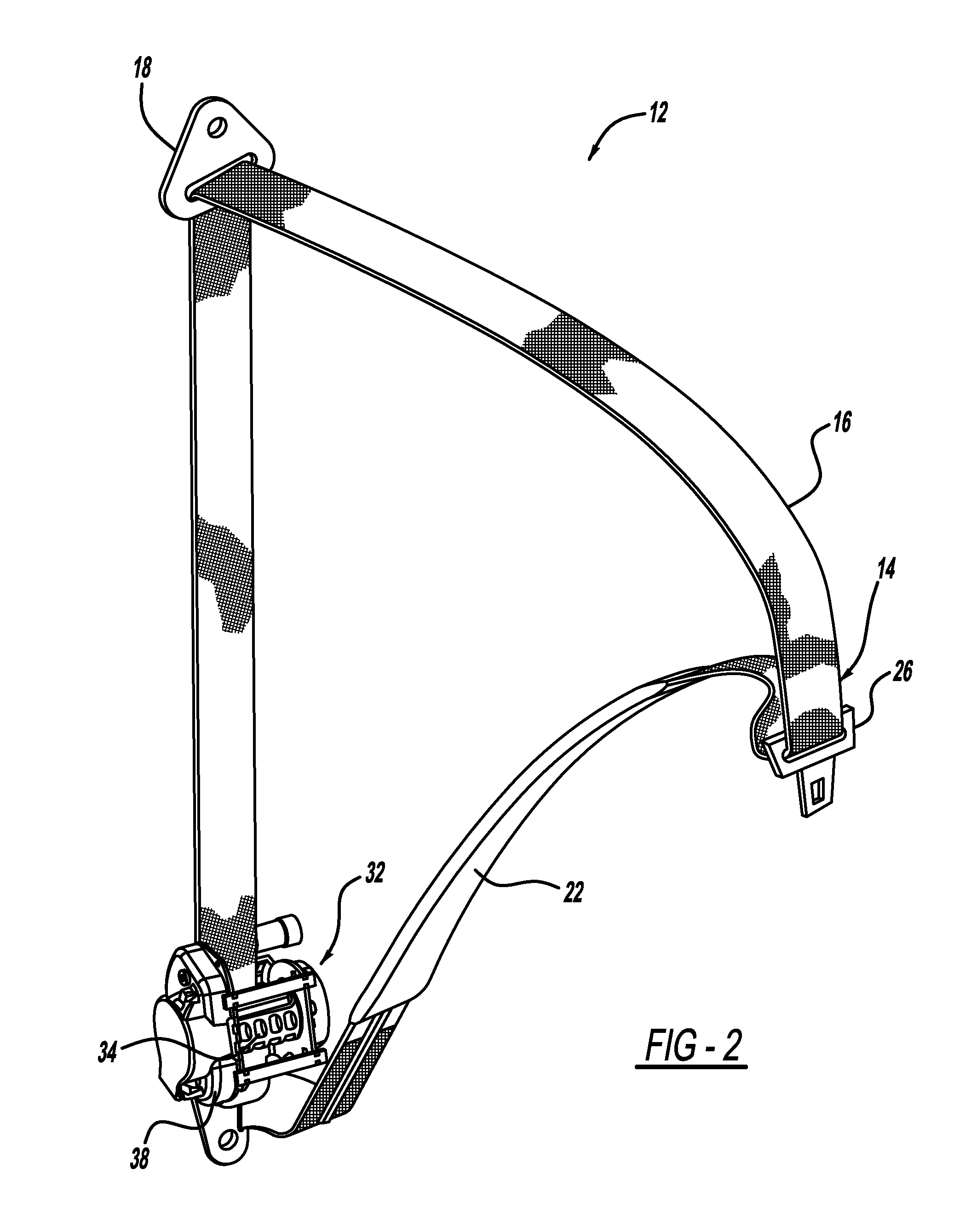
[0020]The seat belt webbing 14 is able to pay-out from a retractor 32 assembly (shown in FIGS. 2 and 3), which is located within the vehicle seat 10 (in an integrated structural seat design) or is coupled structurally to the vehicle body, so that the effe...


PUM


Abstract

A pretensioner assembly for motor vehicle belt restraint systems is provided. The pretensioner assembly includes a tube in fluid communication with a gas generator. An elastic piston disposed within the tube is operable to drive a plurality of balls upon receiving pressurized gas discharged from the gas generator. The piston includes a proximate end and a distal end. The proximate end includes a flexible rim that expands upon receiving pressurized gas from the gas generator, and the distal end includes a flexible rim that expands in response to backpressure from the plurality of balls. The expansion of the flexible rims at the proximate and distal ends of the piston provides a tight seal between the piston and the inner peripheral wall of the tube.

Description

FIELD OF THE INVENTION[0001]The present invention relates generally to seatbelt restraint devices for restraining an occupant of a vehicle, and more particularly, to devices for pretensioning a seatbelt.BACKGROUND OF THE INVENTION[0002]Seatbelt restraint systems for restraining an occupant in a vehicle seat play an important role in reducing occupant injury in vehicle crash situations. Seatbelt restraint systems of the conventional so-called “3-point” variety commonly have a lap belt section extending across the seat occupant's pelvis and a shoulder belt section crossing the upper torso, which are fastened together or are formed by a continuous length of seatbelt webbing. The lap and shoulder belt sections are connected to the vehicle structure by anchorages. A belt retractor is typically provided to store belt webbing and may further act to manage belt tension loads in a crash situation. Seatbelt restraint systems which are manually deployed by the occupant (so-called “active” type...

Claims


Application Information

Patent Timeline
IPC IPC(8): B60R22/46
CPCB60R2022/4642B60R22/4628
Inventor BURROW, JONKELLER, GERALD
Owner AUTOLIV ASP INC
Features
  • Generate Ideas
  • Intellectual Property
  • Life Sciences
  • Materials
  • Tech Scout
  • Unparalleled Data Quality
  • Higher Quality Content
  • 60% Fewer Hallucinations
Learn More