Coupling assembly

a technology of coupling assembly and assembly plate, which is applied in the direction of rod connection, sheet joining, bearings, etc., can solve the problems of adding further complexity to the process, time-consuming, and difficult processes, and achieve the effect of reducing the number of parts required

Inactive Publication Date: 2012-01-12
AIRBUS OPERATIONS LTD
View PDF3 Cites 16 Cited by
  • Summary
  • Abstract
  • Description
  • Claims
  • Application Information

AI Technical Summary

Benefits of technology

[0016]whereby the one or more spherical bearing surfaces permit self-alignment of the setting device to accommodate tilting of the shaft with respect to the head about a central point in two orthogonal directions.
[0017]The coupling assembly is advantageous in that thickness tolerances in the first or second components can be accommodated through adjustment of the axial position of the shaft with respect to the head and setting a desired position by the setting means. The coupling assembly is also advantageous in that angularity between the connection surfaces of the first and second components can be accommodated by the spherical bearing surface(s). The coupling assembly can be standardised for joining a variety of different components, thus reducing the number of parts required in comparison with bespoke butt-straps and associated packers etc.

Problems solved by technology

However, as the butt-straps 3 are typically fitted in various strips across the whole span of the wing, this process can be difficult and time consuming.
This adds further complexity to the process.

Method used


Image

  • Coupling assembly
  • Coupling assembly
  • Coupling assembly

Examples


Embodiment Construction

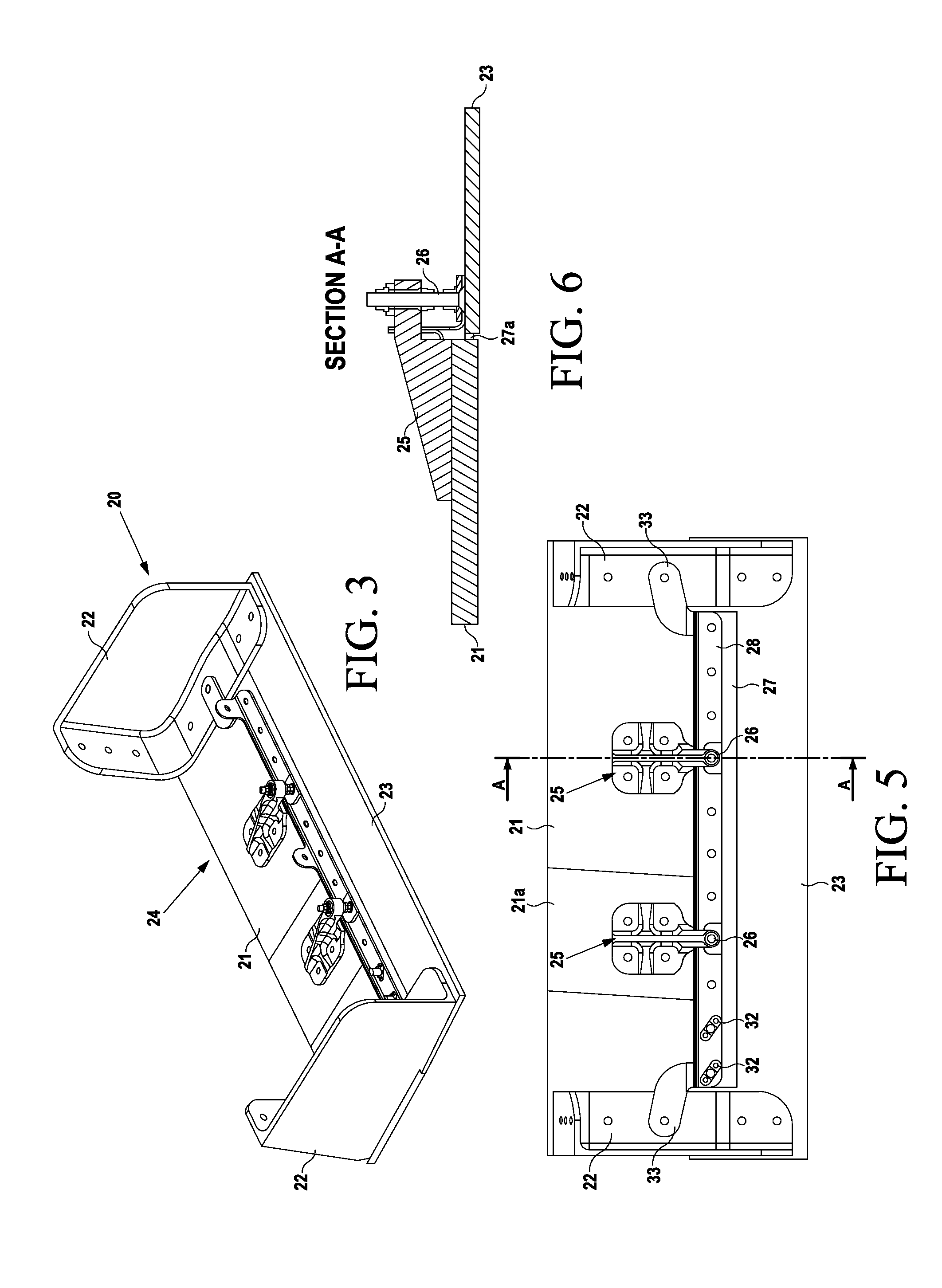
[0038]FIG. 3 shows part of the trailing edge 20 of an aircraft wing. A lower wing cover 21 is attached to ribs 22, and the ribs 22 and the lower wing cover 21 are connected to a rear spar (not shown). A trailing edge panel 23 is also attached to the ribs 22. To achieve a smooth aerodynamic surface, the external surface of the panel 23 and the external surface of the cover 21 must be aligned with each other within a strict tolerance range. In place of a conventional butt-strap, a coupling assembly 24 is used to join the panel 23 to the cover 21.

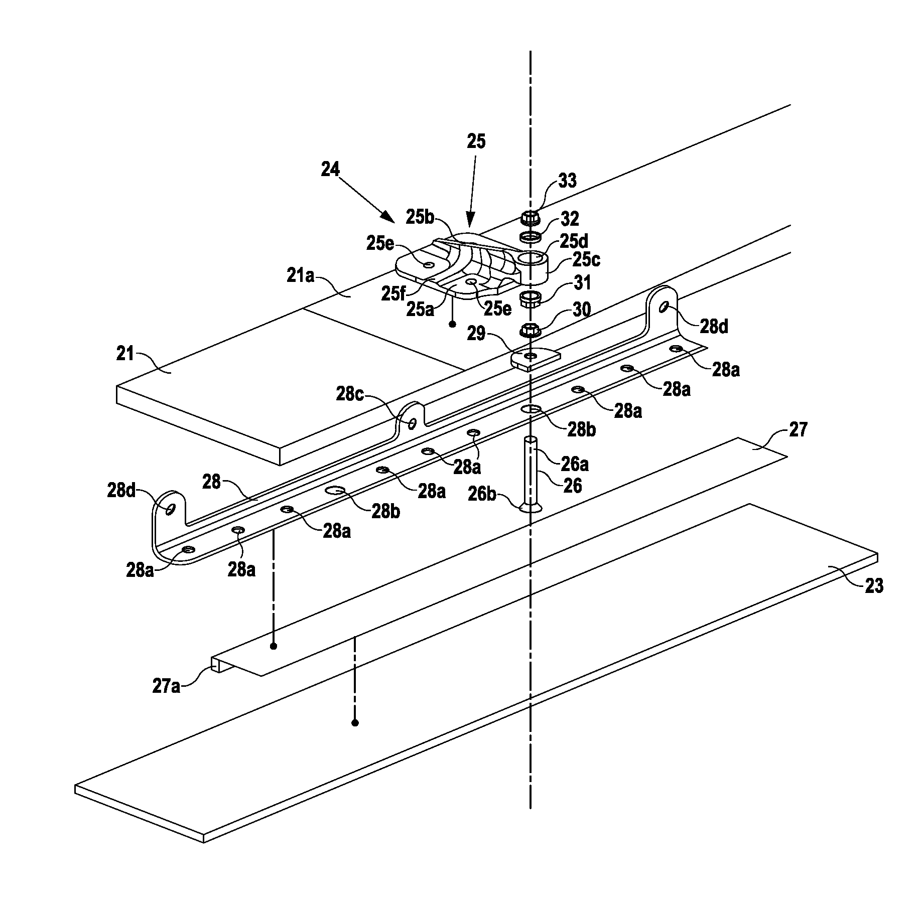
[0039]As best shown in FIG. 4, the coupling assembly 24 includes a bracket 25, a bolt 26, a seal member 27, an L-shaped stiffener 28, a washer 29, a locknut 30, a spherical nut 31, a spherical washer 32 and a spherical nut 33.

[0040]The bracket 25 includes a mounting plate 25a, a bracket arm 25b extending from the mounting plate 25a, and a head 25c having a through bore 25d on the bracket arm 25b. The mounting plate 25a has four fixing holes 25...


PUM

PropertyMeasurementUnit
aerodynamicaaaaaaaaaa
thicknessaaaaaaaaaa
aerodynamic toleranceaaaaaaaaaa

Abstract

A coupling assembly for joining a first component to a second component, the assembly comprising a shaft for connecting to a first component, and a bracket including a mounting plate for connecting to a second component. The bracket has a bracket arm extending from the mounting plate, and a head having a through-bore on the bracket arm. The shaft is received in the through-bore. A setting device acts between the head and the shaft for setting of the position of the shaft with respect to the head in the axial direction of the shaft. The assembly further includes one or more spherical bearing surfaces, which permit self-alignment of the setting device to accommodate tilting of the shaft with respect to the head about a central point in two orthogonal directions. Also, a joint comprising a first component joined to a second component by one or more of the coupling assemblies. Also, a method of forming a joint using one or more of the coupling assemblies.

Description

FIELD OF THE INVENTION[0001]The present invention relates to a coupling assembly for joining components together. The invention also relates to a joint formed using the coupling assembly and a method of forming such a joint.BACKGROUND OF THE INVENTION[0002]Conventional aircraft wings comprise a wing box with front and rear spars. Upper and lower wing covers are attached to the spars and extend between them to form the upper and lower boundaries of the wing box. Leading and trailing edge structures, such as panels or D-nose covers, are typically attached to the upper and lower covers with butt-straps. FIGS. 1 and 2 illustrate conventional butt-strap arrangements.[0003]An upper wing cover 1 is attached to a fixed leading edge structure 2 with a butt-strap 3, a pair of bolts 4, 5 and nuts 9, 10. The butt-strap 3 comprises upper and lower horizontal portions 6, 7 which are joined by a vertical portion 8. The lower portion 6 engages with the internal surface of the cover 1, while the upp...

Claims


Application Information

Patent Timeline
Patent Type & Authority Applications(United States)
IPC IPC(8): B64C1/26F16B5/02B23P11/00B64C1/12
CPCB64C3/28Y10T29/49947Y10T403/19F16B5/025
Inventor COULTER, STEVENHADLEY, PAULHOPKINS, GERAINT
Owner AIRBUS OPERATIONS LTD
Why Eureka
Try Eureka