
Power profiling and auditing consumption systems and methods

a power consumption and consumption technology, applied in the field of power management, can solve problems such as power failure of racks, and achieve the effects of facilitating the maximum utilization of data center resources, accurate and detailed power measurement, and easy assessment of the effectiveness of such strategies

Active Publication Date: 2012-01-12
DALTON DAMIAN +3
View PDF14 Cites 66 Cited by
  • Summary
  • Abstract
  • Description
  • Claims
  • Application Information

AI Technical Summary

Benefits of technology

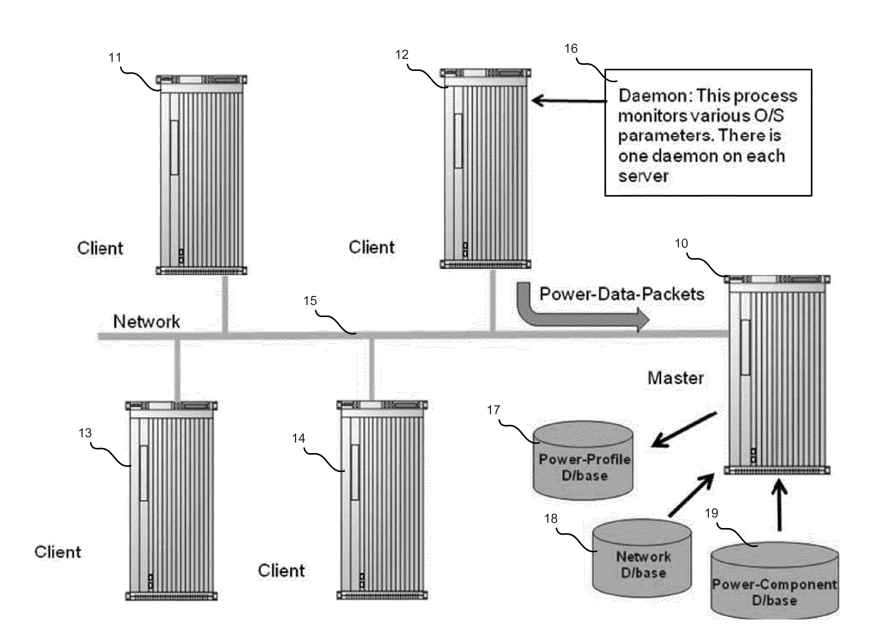
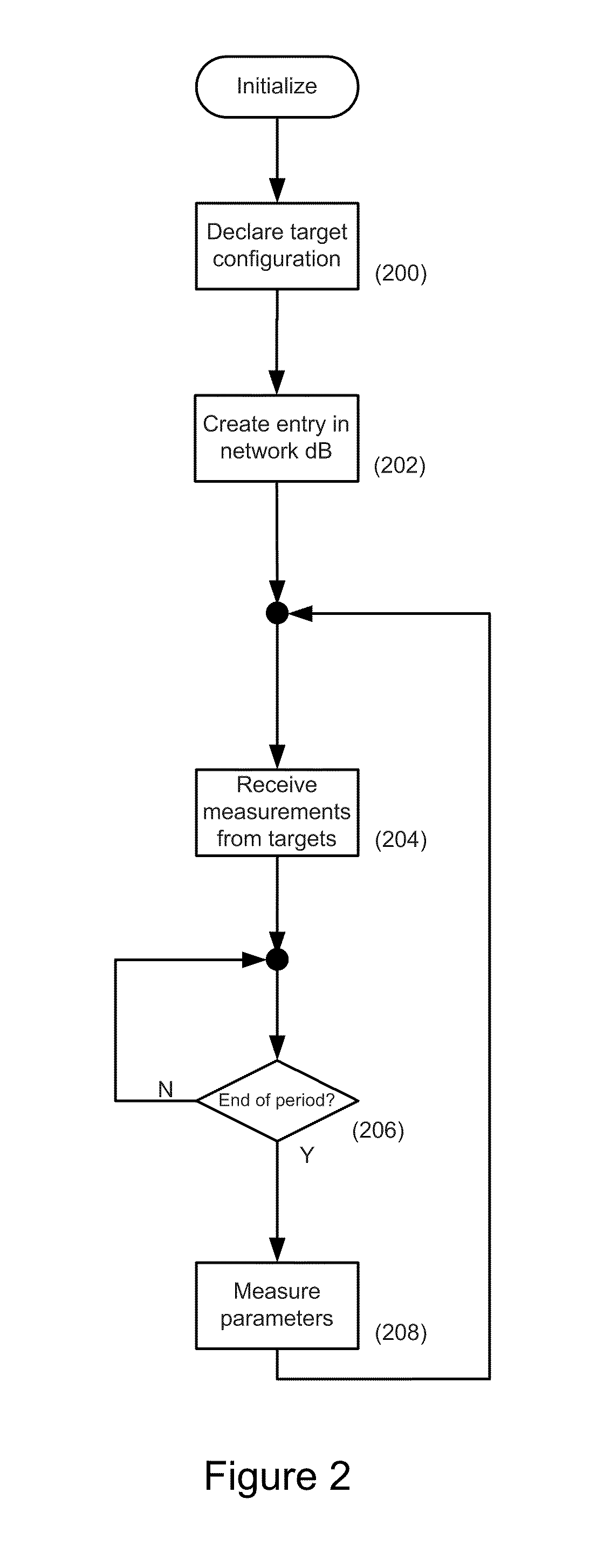
[0013]Certain embodiments of the invention comprise software systems that can be installed in a server network and provide non-intrusive mechanisms (i.e. no extra hardware is required on the computer) for monitoring power consumption while the servers are operating. Software daemons installed on each target server monitor various parameters through the operating system (“O / S”). The value of these parameters may be sampled and / or monitored at the end of a designated time period by the daemons through a series of system calls, typically to one or more O / S functions. These parameters can be used as input variables for various mathematical models describing the power and energy behavior of each respective target server. The target servers act as clients in the overall system and periodically transmit packets containing measured and configured parameters to a monitoring server (“Master Server”) that is often considered a central server. Parameters may have been measured over a designated period of time at each from each individual target server to a Master Server. The Master Server typically maintains power models for each server type in the network and, using these models in conjunction with the parameters that have been received from the target servers, the Master Server can compute an estimate of the power and energy consumption of each individual target server over the designated time period. The power and energy information for all target servers is stored in database so that extensive analysis can be prepared for every server over an extended period of time.
[0014]Certain embodiments of the invention permit accurate determination of server power demand in a rack, thereby facilitating the maximum utilization of the data center resources and circumventing certain issues arising from underestimation server power demand. These issues can result in power failure for the rack.
[0015]Certain embodiments of the invention resolve problems observable in conventional systems by enabling proper energy and power management of a data-center by providing systems and methods that provide accurate and detailed power measurement. With adequate power monitoring, power issues can be identified and quantified, and an informed series of strategies devised to tackle them. The effectiveness of such the strategies can easily be assessed. Further measures to reduce power and costs can be introduced. The operational cost of servers and equipment can be determined and their true total cost of ownership (TOO) ascertained. The cost of running the same application executing on different servers with the same workload, can be investigated. Applications can then be migrated onto the server which offers the best cost / performance metric.
[0016]Moreover, certain embodiments of the invention inform choice when a data center is being upgraded. The most efficient servers and equipment can be chosen based on real, historic data, and the required capacity of all support systems accurately estimated. A wider range of power saving actions are available because power monitoring of the servers can be performed in real-time rather than being limited to analysis of power logs that are generated over a period of time. Because power information can be readily and timely acquired, immediate action can be taken to direct cooling to specific hot-spots along with other automated responses, thereby preventing adverse operating conditions and maintain optimal performance.

Problems solved by technology

These issues can result in power failure for the rack.

Method used


Image

  • Power profiling and auditing consumption systems and methods
  • Power profiling and auditing consumption systems and methods
  • Power profiling and auditing consumption systems and methods

Examples


Embodiment Construction

[0027]Embodiments of the present invention will now be described in detail with reference to the drawings, which are provided as illustrative examples so as to enable those skilled in the art to practice the invention. Notably, the figures and examples below are not meant to limit the scope of the present invention to a single embodiment, but other embodiments are possible by way of interchange of some or all of the described or illustrated elements. Wherever convenient, the same reference numbers will be used throughout the drawings to refer to same or like parts. Where certain elements of these embodiments can be partially or fully implemented using known components, only those portions of such known components that are necessary for an understanding of the present invention will be described, and detailed descriptions of other portions of such known components will be omitted so as not to obscure the invention. In the present specification, an embodiment showing a singular compon...


PUM


Abstract

Systems and methods for estimating power consumption in a network of computing devices are described. Operational information of a target server is periodically received and compared to benchmark data of a model of the target server. The operational information comprises performance data of the target server during a predefined time interval. Power consumption of the target server is estimated using the performance and benchmark data. The benchmark data is recalibrated if an error in the estimated power consumption is detected. An agent installed on the target server for collecting performance data is described. The target server can be a virtualized server, in which case, the agent acquires at least some of the performance data from a hypervisor of a physical server that hosts the target server.

Description

CROSS-REFERENCE TO RELATED APPLICATIONS [0001]The present Application claims priority from Irish Patent Application No. 2010 / 0424, filed Jul. 9, 2010, and from U.S. Provisional Patent Application No. 61 / 454,741 filed Mar. 21, 2011, and both of these applications are expressly incorporated by reference herein for all purposes.BACKGROUND OF THE INVENTION[0002]1. Field of the Invention[0003]The present invention relates generally to power management and more particularly to power usage estimation and monitoring systems.[0004]2. Description of Related Art[0005]Power consumption of servers, memory devices and network equipment is a major issue of concern in the design and operation of data centers. Apart from consuming electrical power, servers and associated equipment must be cooled to ensure that they operate in the envelope of conditions for which they have been designed. Operating outside this envelope reduces the life-span and increases the failure rate of these devices. For every 2...

Claims


Application Information

Patent Timeline
IPC IPC(8): G06F1/00
CPCG06F11/3062G06F11/328G06F11/3447Y02B60/165G06F11/3466G06F2201/815G06F11/3428Y02D10/00
Inventor DALTON, DAMIANVADHER, ABHAYMCCARTHY, ANDREWSTEGER, CHRISTIAN
Owner DALTON DAMIAN
Learn More