Torch Flow Regulation Using Nozzle Features

a technology of nozzles and nozzles, applied in welding/cutting media/materials, manufacturing tools, welding apparatus, etc., can solve the problems of consumable failures, poor performance, premature failure of consumables, etc., and achieve the effect of reducing the amount of time operators spend and reducing the total operating cost of plasma arc torch

Active Publication Date: 2012-01-19
HYPERTHERM INC
View PDF3 Cites 59 Cited by
  • Summary
  • Abstract
  • Description
  • Claims
  • Application Information

AI Technical Summary

Benefits of technology

[0006]A need, therefore, exists to minimize the required number of consumables, for example, nozzles, swirl rings, and retaining caps, which are required for various different plasma arc torch parameters (e.g., shield flow and / or cooling flow rates, amperage, material type or application). Consumable part commonality can reduce the amount of time operators spend determining which consumable combination is correct for specific plasma torch parameters. Also, the total operating cost of a plasma arc torch will decrease because the probability that consumables will fail prematurely or perform poorly due to incorrect matchup of consumables will decrease because a single consumable can be used for many different torch parameters.

Problems solved by technology

Also, the total operating cost of a plasma arc torch will decrease because the probability that consumables will fail prematurely or perform poorly due to incorrect matchup of consumables will decrease because a single consumable can be used for many different torch parameters.

Method used


Image

  • Torch Flow Regulation Using Nozzle Features
  • Torch Flow Regulation Using Nozzle Features
  • Torch Flow Regulation Using Nozzle Features

Examples


Embodiment Construction

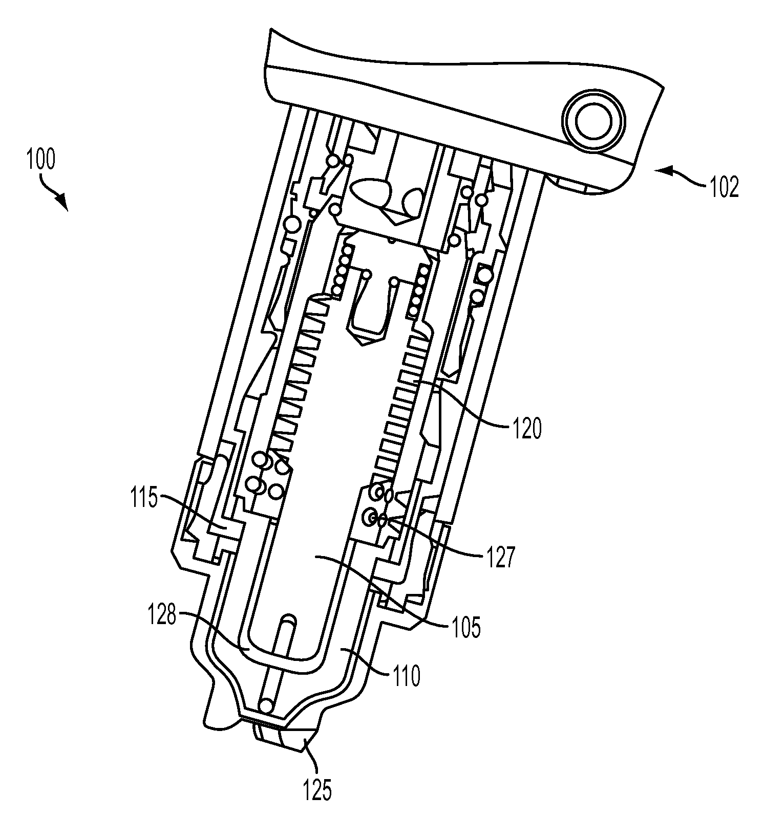
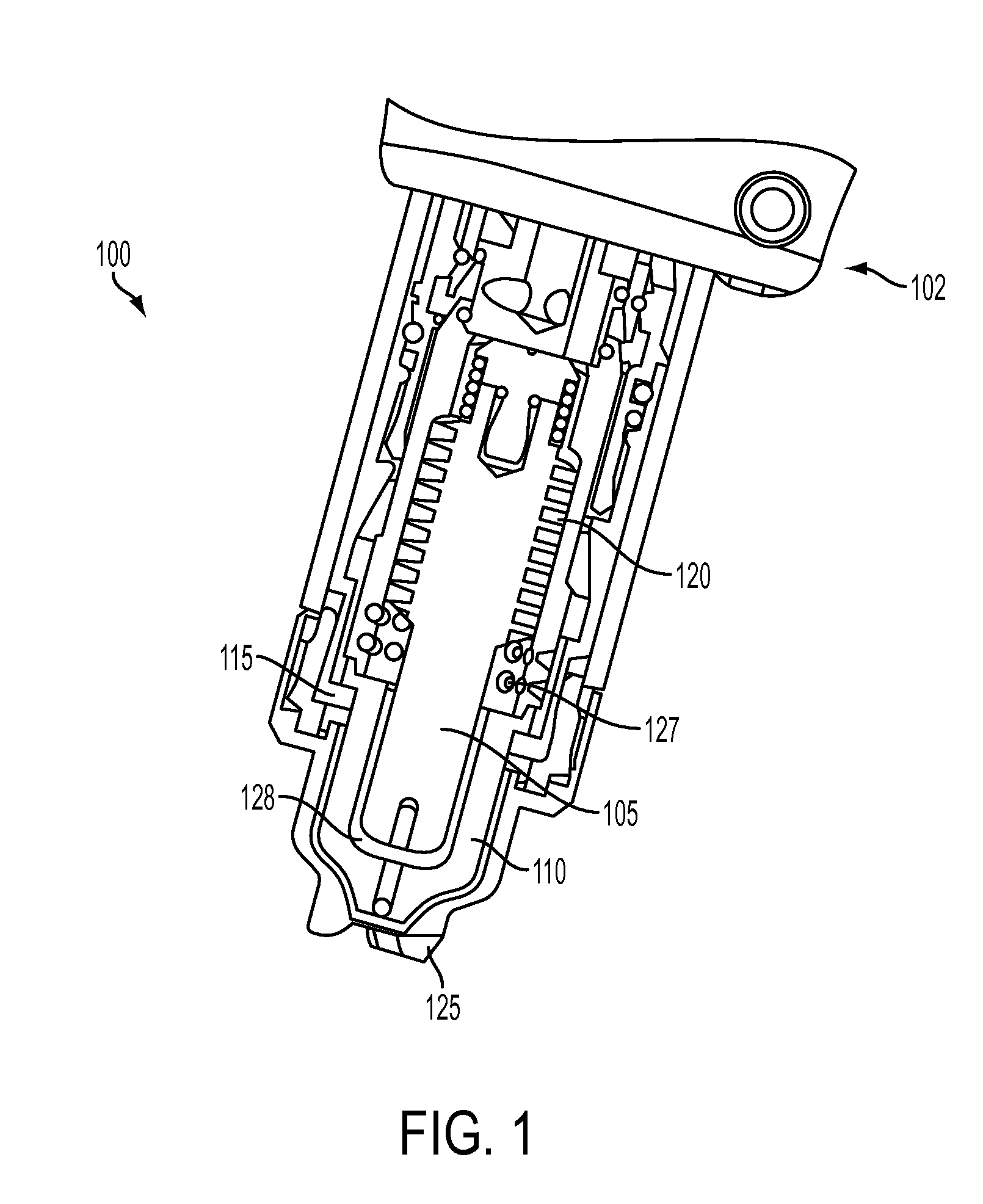
[0039]FIG. 1 shows a cross-sectional view of a plasma arc torch 100. A plasma torch tip is comprised of a variety of different consumables, for example, an electrode 105, a nozzle 110, a retaining cap 115, a swirl ring 120, or a shield 125. The torch body 102 supports the electrode 105, which has a generally cylindrical body. The torch body 102 also supports the nozzle 110. The nozzle 110 is spaced from the electrode 105 and has a central exit orifice mounted within the torch body 102. The swirl ring 120 is mounted to the torch body 102 and has a set of radially offset (or canted) gas distribution holes 127 that impart a tangential velocity component to the plasma gas flow causing it to swirl. The shield 125, which also includes an exit orifice, is coupled (e.g., threaded) to the retaining cap 115. The retaining cap 115 is coupled (e.g., threaded) to the torch body 102. The torch and torch tip include electrical connections, passages for cooling, passages for arc control fluids (e.g...


PUM

PropertyMeasurementUnit
diameteraaaaaaaaaa
diameteraaaaaaaaaa
angleaaaaaaaaaa

Abstract

A nozzle for a plasma arc torch includes a body having a first end and a second end. The nozzle also includes a plasma exit orifice located at the first end of the body. A flange is located at the second end of the body. The flange is adapted to mate with a corresponding consumable. The flange is configured to selectively block at least one gas passage in the corresponding consumable to establish a gas flow relative to the nozzle body.

Description

RELATED APPLICATIONS[0001]This application claims the benefit of and priority to U.S. Provisional Application No. 61 / 365,202, filed Jul. 16, 2010, the entirety of which is hereby incorporated herein by reference.TECHNICAL FIELD[0002]The present invention relates generally to plasma arc cutting torches, and more particularly, to regulating torch flow using nozzle features.BACKGROUND[0003]Welding and plasma arc torches are widely used in the welding, cutting, and marking of materials. A plasma torch generally includes an electrode and a nozzle having a central exit orifice mounted within a torch body, electrical connections, passages for cooling, and passages for arc control fluids (e.g., plasma gas). Optionally, a swirl ring is employed to control fluid flow patterns in the plasma chamber formed between the electrode and nozzle. In some torches, a retaining cap can be used to maintain the nozzle and / or swirl ring in the plasma arc torch. The torch produces a plasma arc, a constricted...

Claims


Application Information

Patent Timeline
Patent Type & Authority Applications(United States)
IPC IPC(8): B23K9/16
CPCH05H2001/3457H05H1/34H05H1/3457H05H1/3468
Inventor ROBERTS, JESSETWAROG, PETERDUAN, ZHENGKIM, SUNG JE
Owner HYPERTHERM INC
Why Eureka
Try Eureka