Planar illumination device and image display apparatus

a technology of image display and illumination device, which is applied in the direction of static indicating device, lighting and heating apparatus, instruments, etc., can solve the problems of liquid crystal display apparatus performance, blur, so-called motion blur, etc., and achieve excellent moving image display performance and simple and easy configuration.

Inactive Publication Date: 2012-01-19
PANASONIC CORP
View PDF9 Cites 3 Cited by
  • Summary
  • Abstract
  • Description
  • Claims
  • Application Information

AI Technical Summary

Benefits of technology

[0017]According to the planar illumination device of the present invention, it is possible to emit the light from the light sources through the light emitting surface, with the light guided linearly by the prismatic structures. Therefore, it is possible to illuminate an object to be illuminated, such as an image display panel, for each band-shaped region with a simple and easy configuration using one light guide plate. Further, according to the image display apparatus of the present invention, a high-quality image display with excellent moving image display performance can be achieved by controlling the emission of the light sources at a specific timing using this illumination device.

Problems solved by technology

One of the problems in the performance of the liquid crystal display apparatus is blur, so-called motion blur, that appears when moving images are displayed.

Method used


Image

  • Planar illumination device and image display apparatus
  • Planar illumination device and image display apparatus
  • Planar illumination device and image display apparatus

Examples


embodiment 1

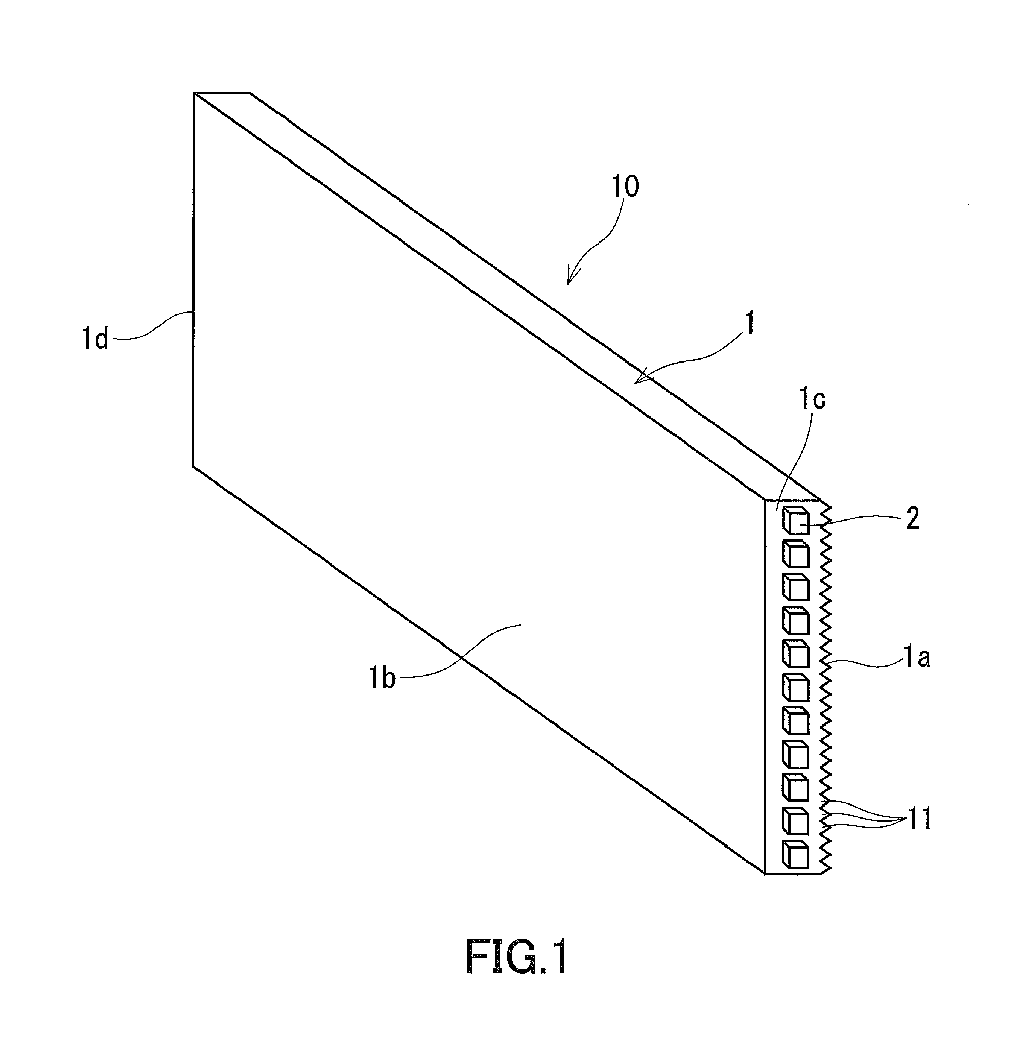
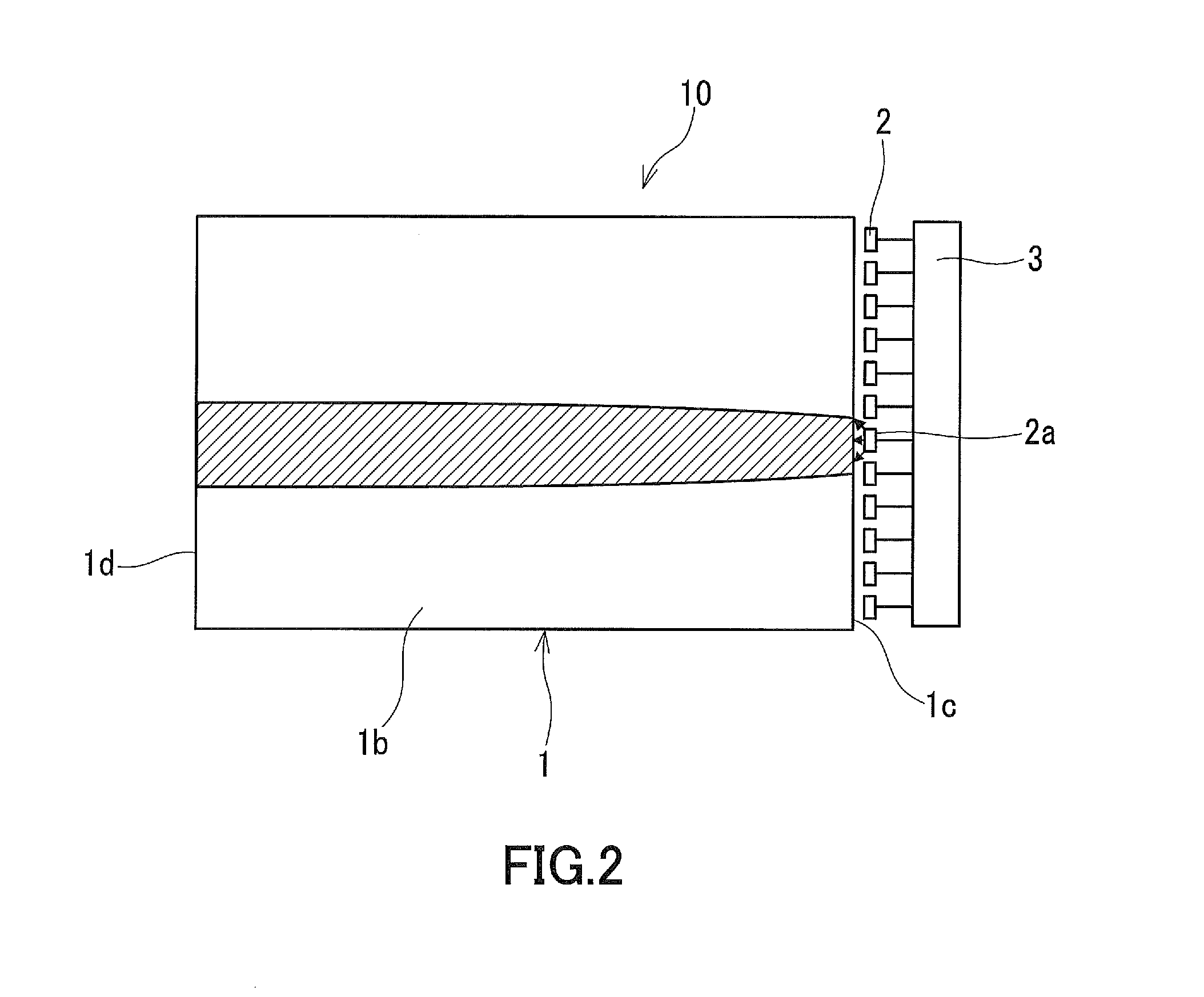
[0024]FIG. 1 and FIG. 2 show a planar illumination device 10 according to Embodiment 1 of the present invention. This planar illumination device 10 is provided with a light guide plate 1, a plurality of light sources 2 that are disposed beside the light guide plate 1, and a brightness controller 3 connected to the light sources 2.

[0025]The light guide plate 1 has a shape of a substantially elongated rectangular plate. One main surface of the light guide plate 1 forms a first surface 1a, and the other main surface that faces opposite to the first surface 1a forms a second surface 1b. On the first surface 1a, a plurality of prismatic structures 11 are formed so as to be arrayed in parallel and in series to each other. In this embodiment, the array direction of the prismatic structures 11 is the short direction of the light guide plate 1, and the prismatic structures 11 extend in the longitudinal direction of the light guide plate 1. In other words, the longitudinal direction of the li...

embodiment 2

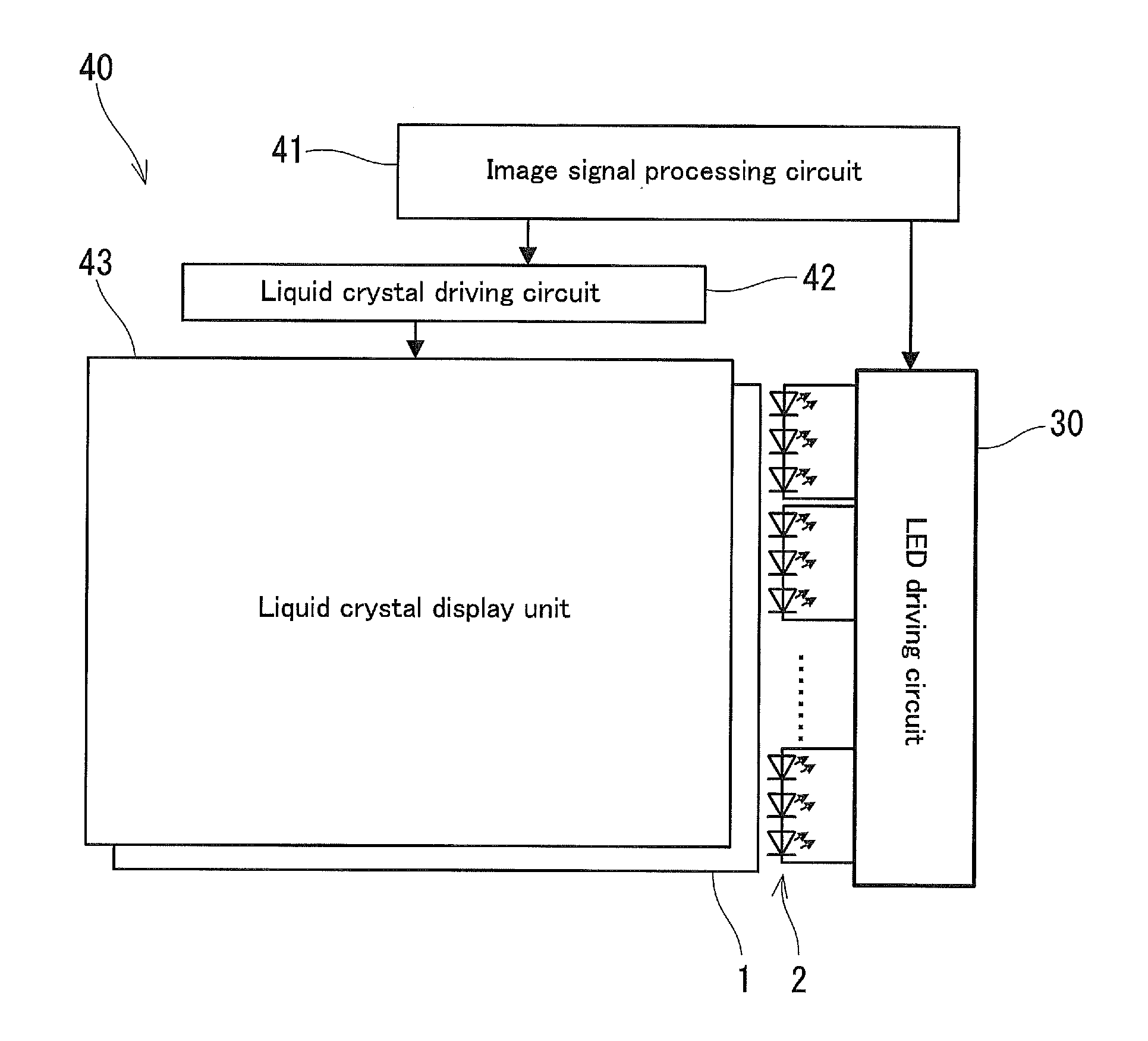
[0044]Next, an image display apparatus according to Embodiment 2 of the present invention is described. The image display apparatus of this embodiment is a liquid crystal display apparatus having a liquid crystal panel as an image display panel. The liquid crystal display apparatus according to Embodiment 2 uses the planar illumination device described in Embodiment 1 as a backlight device, and selectively causes a corresponding portion to blink in synchronization with image signals. This allows motion blur to be reduced, and enables the moving images display quality to be improved. The array direction of prismatic structures may be the vertical direction or the horizontal direction.

[0045]FIG. 4 is a block diagram showing a main configuration of a liquid crystal display apparatus 40 according to Embodiment 2. This liquid crystal display apparatus 40 is provided with the planar illumination device including the light guide plate 1, and the liquid crystal panel disposed on the side of...


PUM


Abstract

A planar illumination device (10) is provided with: a light guide plate (1) having a first surface (1a) and a second surface (1b); a plurality of light sources (2); and a brightness controller. A plurality of prismatic structures (11) are arrayed on the first surface (1a). The light sources (2) are arranged in the same direction as the array direction of the prismatic structures so as to radiate light toward an edge surface (1c) of the light guide plate (1). The brightness controller varies brightness distribution on a light emitting surface of the light guide plate (1) in the array direction of the prismatic structures (11) by controlling light emission of the light sources (2).

Description

TECHNICAL FIELD[0001]The present invention relates to a planar illumination device and an image display apparatus using the planar illumination device.BACKGROUND ART[0002]Thin and lightweight liquid crystal display apparatuses capable of displaying images are known as an image display apparatus. Such liquid crystal display apparatuses have spread rapidly due to the development of image enhancement technology and the price reduction resulting from the progress of production technology. They are now widely used for a monitor of personal computers, a TV receiver, etc.[0003]Transmissive liquid crystal display apparatuses are used commonly as a liquid crystal display apparatus. Such a transmissive liquid crystal display apparatus is provided with a planar illumination device called a backlight device, and forms images by allowing illumination light from the planar illumination device to be spatially modulated through a liquid crystal panel.[0004]One of the problems in the performance of ...

Claims


Application Information

Patent Timeline
Patent Type & Authority Applications(United States)
IPC IPC(8): G09G5/10H05B37/02F21V7/22
CPCG02B6/0038G02F1/133615G02B6/0073G02B6/0068
Inventor YAMAGUCHI, HIROSHI
Owner PANASONIC CORP
Why Eureka
Try Eureka