Liquid accommodating container, tank unit, and liquid ejecting system
- Summary
- Abstract
- Description
- Claims
- Application Information
AI Technical Summary
Benefits of technology
Problems solved by technology
Method used
Image
Examples
first example
A. First Example
A-1. Configuration of Liquid Ejecting System
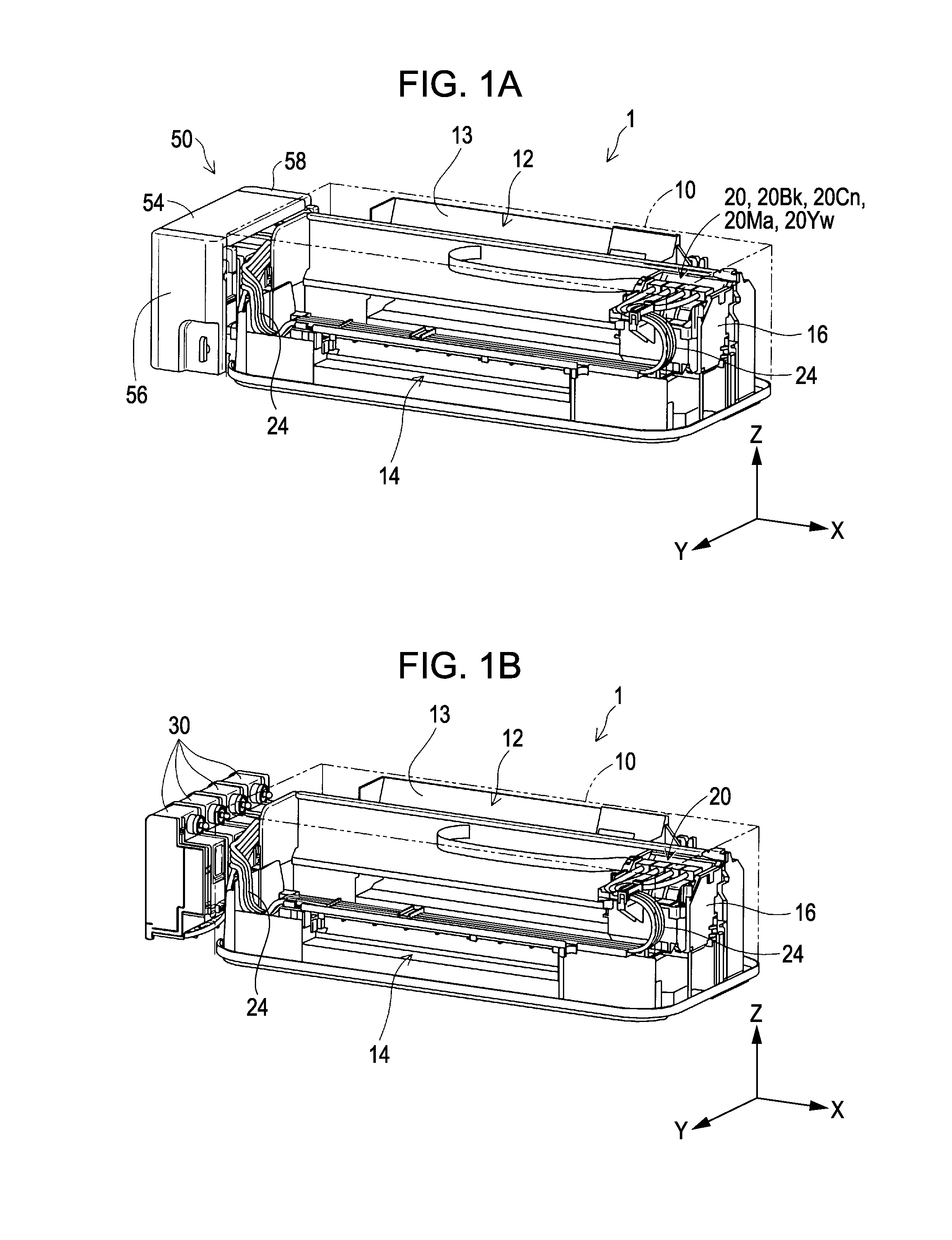
[0051]FIGS. 1A and 1B are diagrams for describing a liquid ejecting system 1 of the first example. FIG. 1A is an exterior perspective view of the liquid ejecting system 1. FIG. 1B is an exterior perspective view of the liquid ejecting system 1 and is a diagram illustrating liquid accommodating containers 30 of the first example of the invention. In addition, in FIGS. 1A and 1B, X, Y, and Z axes being right angles to each other are shown in order to specify a direction. In addition, also with respect to the subsequent drawings, the X, Y, and Z axes are shown as necessary.
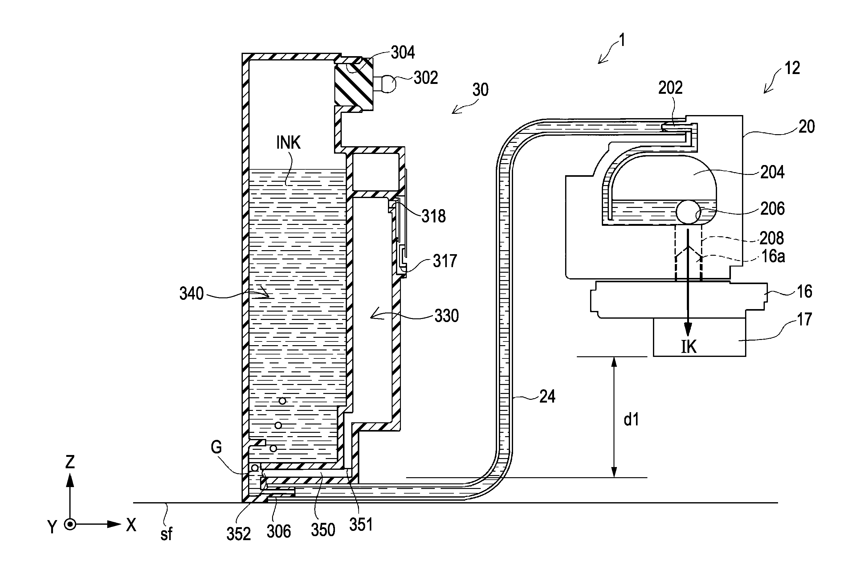
[0052]As shown in FIG. 1A, the liquid ejecting system 1 includes an ink jet printer 12 (also simply referred to as a “printer 12”) as a liquid ejecting apparatus, and a tank unit 50. The printer 12 includes a paper feed section 13, a paper discharge section 14, a carriage 16 and four sub-tanks 20. The four sub-tanks 20 contain ink of different colors. Specif...
second example
B. Second Example
[0123]FIG. 18 is an exploded perspective view of an ink tank 30a of the second example. FIG. 19 is a perspective view of a tank main body 32a of the second example. This example is different from the first example in that one ink tank 30a is provided with two flow paths opened to the air 300 and two liquid accommodating chambers 340 (FIG. 4). In addition, with respect to the same configuration as that in the first example, the same reference numeral is applied and explanation is omitted. Further, a positional relationship between the liquid injection port 304, the air-side opening 351, the liquid-side opening 352, and the port opened to the air 318, which the ink tank 30a of the second example includes, is the same as the positional relationship (FIGS. 9A to 11B, 13A, and 13B) in the first example.
[0124]As shown in FIG. 18, the ink tank 30a includes the tank main body 32a, two films 34, two sheet members 316, the film 322, two plug members 302, and cover members 42 ...
first modified example
C-1. First Modified Example
[0129]In the above examples, the air accommodating chamber 330 is provided with the upper accommodating chamber 337 of a rectangular parallelepiped shape, the lower accommodating chamber 339 of a rectangular parallelepiped shape having volume different from that of the upper accommodating chamber 337, and the communication flow path 338 making the upper and lower accommodating chambers communicate with each other. However, the shape of the air accommodating chamber 330 is not limited to thereto. That is, it is acceptable if it is a configuration having the given volume capable of retaining ink flowed back from the liquid accommodating chamber 340. For example, the air accommodating chamber 330 may also be configured only by one chamber of a rectangular parallelepiped shape or may also have a configuration having three or more of accommodating chambers.
PUM
 Abstract
Description
Claims
Application Information
 - R&D
- Intellectual Property
- Life Sciences
- Materials
- Tech Scout
- Unparalleled Data Quality
- Higher Quality Content
- 60% Fewer Hallucinations
Browse by: Latest US Patents, China's latest patents, Technical Efficacy Thesaurus, Application Domain, Technology Topic, Popular Technical Reports.
© 2025 PatSnap. All rights reserved.Legal|Privacy policy|Modern Slavery Act Transparency Statement|Sitemap|About US| Contact US: help@patsnap.com


