Projection type display device

a display device and projection type technology, applied in the field of projection type display devices, can solve the problems of air filter clogging, high ventilation resistance, air filter clogging, etc., and achieve the effect of suppressing the temperature rise of optical components and preventing dust particles from becoming attached

Inactive Publication Date: 2012-01-19
NEC DISPLAY SOLUTIONS LTD
View PDF2 Cites 82 Cited by
  • Summary
  • Abstract
  • Description
  • Claims
  • Application Information

AI Technical Summary

Benefits of technology

[0018]According to this aspect, it is possible to reliably prevent dust particles from becoming attach

Problems solved by technology

However, because the air filter having a fine mesh collects dust particles in a middle or large particle size, too, the air filter tends to be clogged and has a high ventilation resistance.
Furthermore, if the device is installed in adverse dust particle environments, the air filter is sometimes clogged even though a large-sized air filter is used.
When the air filter is clogged, it is not possible to deliver sufficient tempering air to components in the inside of the device, causing temperature rises in the components, so that the lifetime of the components shortens.
Many optical components are particularly sensitive to temperature, and they deteriorate considerably due to temperature rises, causing color irregularities or a reduction in brightness in projection images.
In addition, in adverse dust particle environments, it is also likely to clog the air filter.
On the other hand, the structure disclosed in Patent Document 2 does not operate in the case where there are no dust particles near the light tunnel or color wheel, and if dust particles are present, the structure can reduce the attachment of dus

Method used


Image

  • Projection type display device
  • Projection type display device
  • Projection type display device

Examples


first embodiment

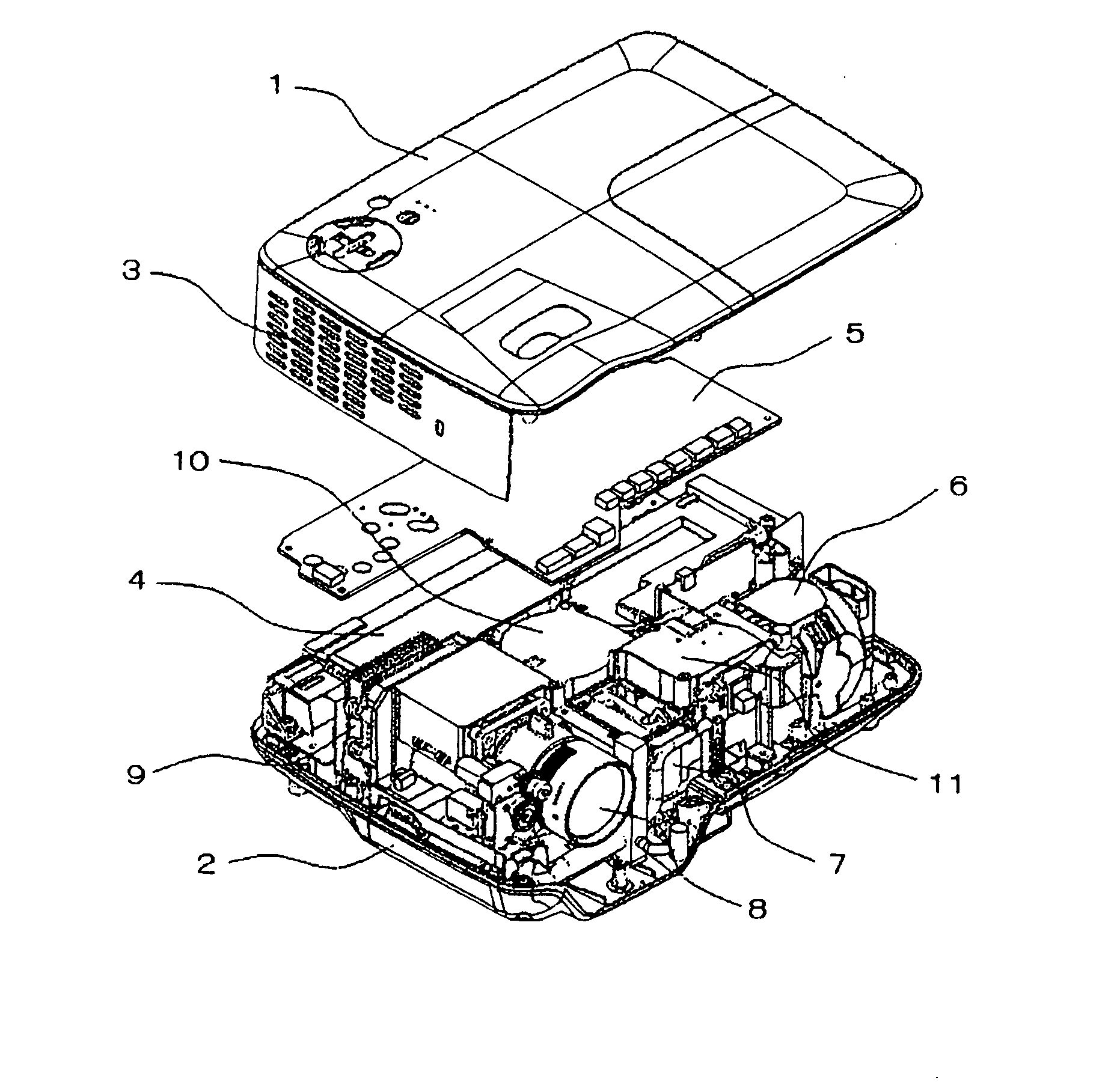
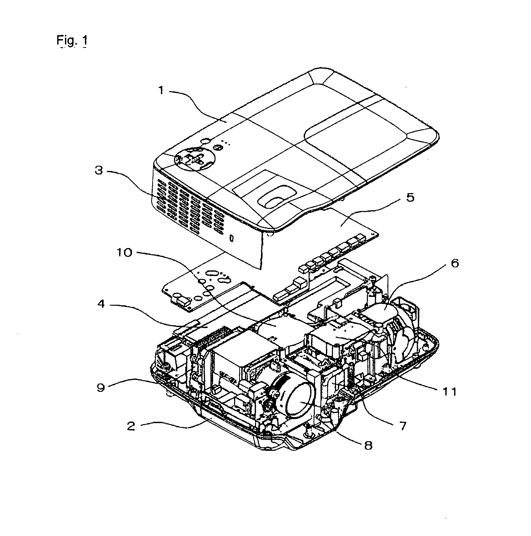
[0077]FIG. 1 is a perspective view depicting a projection type display device according to an embodiment of the present invention shown in the exploded state. The display device according to this embodiment includes upper cabinet 1 and lower cabinet 2 in a recessed shape, having power supply unit 4, main substrate 5, lamp unit 6, optical engine 7, projection lens 8, DMD unit 9, sirocco fan 10, duct 11, and the like in the inside of the space formed by combining upper cabinet 1 and lower cabinet 2. In addition, in FIG. 1, the display device is shown, from which upper cabinet 1 and main substrate 5 are removed upward.

[0078]When electric power is supplied from the outside of the display device to power supply unit 4, the power supply part in power supply unit 4 supplies electric power to a ballast (not shown) and main substrate 5. When a user of the device presses a button switch (not shown) provided on the rear of the right side surface of upper cabinet 1, the device is activated, and...

second embodiment

[0114]FIG. 10 is a schematic diagram depicting a second embodiment of the present invention. This is an example in which the internal structure of the first embodiment is modified (more particularly, a cross sectional view of FIG. 9).

[0115]In this embodiment, heat exchanger 12 is not provided, and the heat of the air in the inside of the enclosed space is dissipated to the outside of the enclosed space only by heat dissipation from the shielding wall surfaces. Although the point is the same as in the first embodiment in that sirocco fan 19 blows tempering air to light tunnel 20, a part of the tempering air after having been blown partially passes through the inside of light tunnel 20, and the rest moves to enclosed space A through ventilation hole 41, and opening (ventilation gap) 43 provided on the upper part. The diameter of ventilation hole 41 and the gap between the circumferential end surface of opening 43 and the outer surface of light tunnel 20 are small, and as a result, tem...

third embodiment

[0116]FIG. 11 is a schematic diagram depicting a third embodiment of the present invention. This is an embodiment in which the internal structure of the first embodiment is modified (more particularly, a cross sectional view of FIG. 9).

[0117]In this embodiment, heat exchanger 12 is not provided, and the heat of the air in the inside of the enclosed space is dissipated to the outside of the enclosed space only by heat dissipation from the shielding wall surfaces. Although the overall flow of tempering air in the inside of the enclosed space is almost the same as that in the first embodiment, in this embodiment, ventilation hole 41 and opening 43 as shown in FIG. 9 are not provided, and the cooling of the motor shaft in the center takes priority over the outer circumference of color wheel 24. In other words, all the tempering air after having been blown to light tunnel 20 by sirocco fan 19 passes through the inside of light tunnel 20, and the air first blows against the motor shaft in...


PUM


Abstract

It is possible to reliably prevent dust particles from becoming attached to optical components and it is also possible to suppress temperature rises in optical components. A projection type display device according to the present invention includes a plurality of optical components (20, 21, 24, 30, and so on), a hollow structure (45, 50, or the like), and an air blow source (19, 46, or the like). The plurality of optical components are provided along the optical axis direction of light emitted from a light source. The hollow structure includes optical components (20, 24) that are to be protected from the attachment of dust particles to optical components among the plurality of optical components, and forms an enclosed space separated from the surroundings. Then, the source that blows air is provided in the inside of the enclosed space to circulate the internal air for cooling targets.

Description

TECHNICAL FIELD[0001]The present invention relates to a projection type display device equipped with a dustproof structure that prevents dust particles from attaching to optical components.BACKGROUND ART[0002]In conventional projection type display devices, there is a device that obtains dustproof effect by covering the entire device with a protection case (for example, see Patent Document 1). In addition, as devices that target particular components mounted on the device, not the entire device, there is a device that reduces the attachment of dust particles to a light tunnel or color wheel, (Patent Document 2), and there is a device that cleans a rod integrator soiled due to the attachment of dust particles (Patent Document 3).[0003]In the following, these examples of conventional dustproof techniques will be described.[0004]The technique disclosed in Patent Document 1 is one in which the entire device is enclosed and dust-proofed using a protection cabinet mounted with an air filt...

Claims


Application Information

Patent Timeline
IPC IPC(8): G03B21/16
CPCG03B21/16G03B21/14
Inventor NISHIMURA, YOSHIFUMIOKADA, TAKAYUKI
Owner NEC DISPLAY SOLUTIONS LTD
Why Eureka
Try Eureka