
Lens barrel support structure and optical device

a technology of optical devices and support structures, applied in the direction of mountings, optics, instruments, etc., can solve the problems of increasing the number of parts, difficult to accurately attach the lens barrel to the main body of the optical device, and the strain is more likely to occur in the member during the attachment, so as to achieve effective dispersion of any force exerted and increase the impact resistance

Active Publication Date: 2012-01-19
PANASONIC CORP
View PDF1 Cites 4 Cited by
  • Summary
  • Abstract
  • Description
  • Claims
  • Application Information

AI Technical Summary

Benefits of technology

"The invention provides a lens barrel support structure that attaches the lens barrel to the main body of the optical device, effectively dispersing any force exerted on the lens barrel and making the optical device more impact resistant. The structure includes a base frame and a lens barrel with attachment portions and a receiver fixedly coupled to the body frame. The receiver and stopper are disposed spaced apart and define a gap that allows the receiver to contact the stopper."

Problems solved by technology

With these techniques, however, an elastic member or other such cushioning member must be disposed between the lens barrel and the main body of the optical device, and this increases the number of parts.
However, when a lens barrel and the main body of the optical device are fixed at four or more locations, strain is more likely to occur in the members during attachment than when they are fixed at three locations.
As a result, it is difficult to attach the lens barrel accurately to the main body of the optical device.

Method used


Image

  • Lens barrel support structure and optical device
  • Lens barrel support structure and optical device
  • Lens barrel support structure and optical device

Examples


first embodiment

[0030]1-1. Overall Configuration

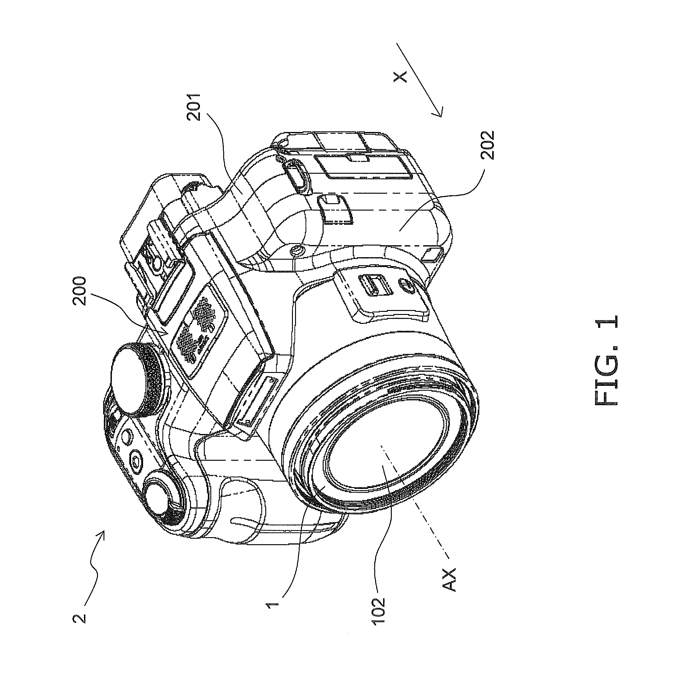
[0031]The digital camera 2 according to an embodiment of the present invention will now be described through reference to the drawings.

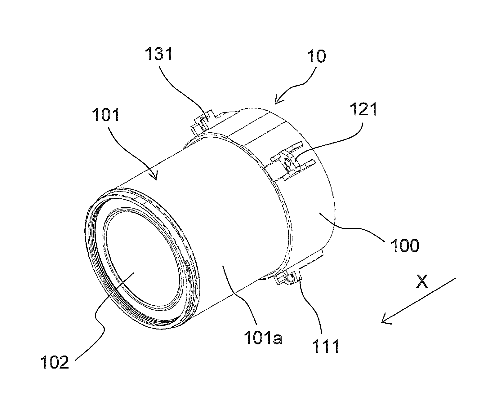
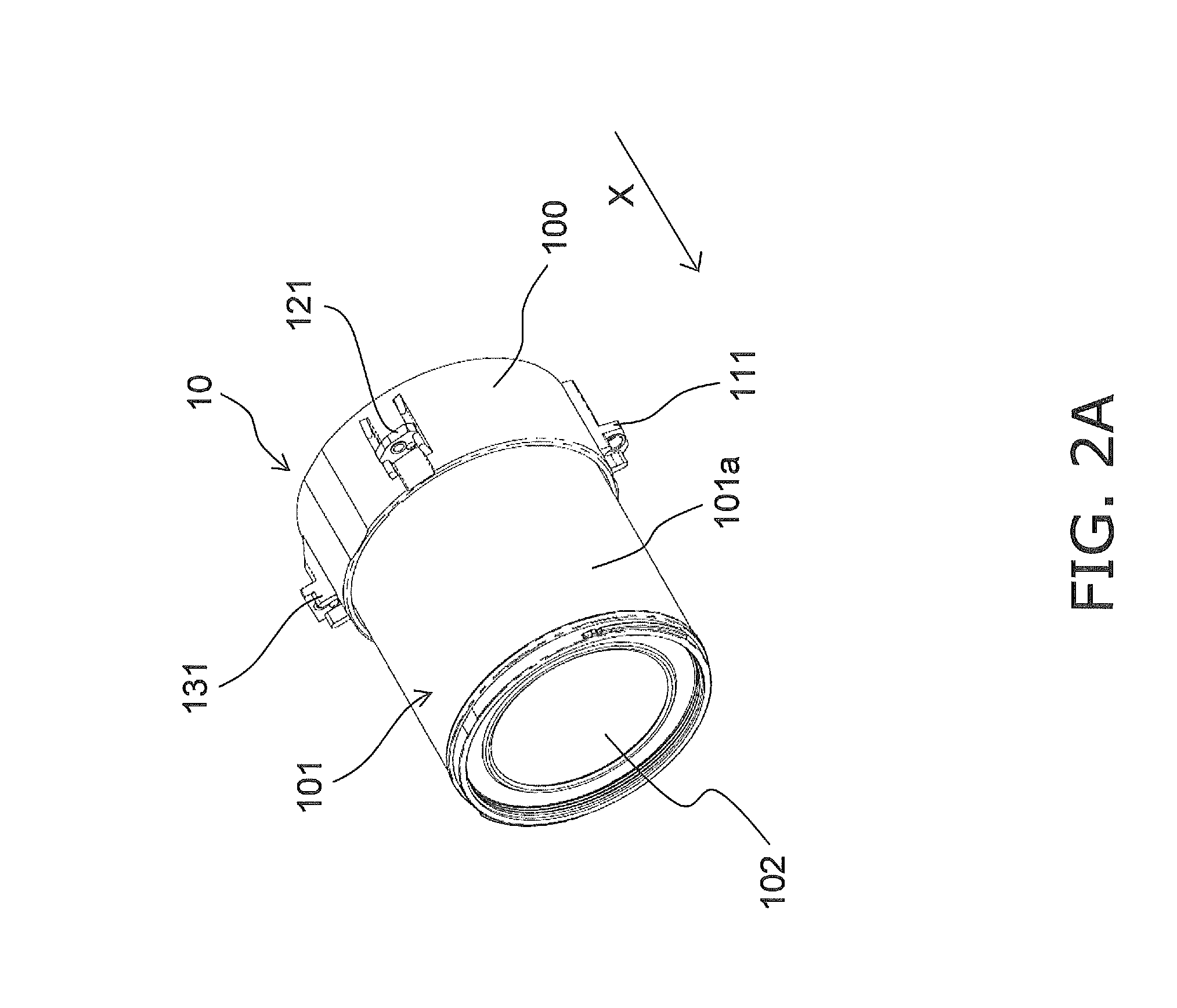
[0032]FIG. 1 is an oblique view of a digital camera 2 (an example of an optical device) in the first embodiment. In this embodiment, an optical device is described by using the digital camera 2 as an example, but the optical device can be a silver halide camera, a digital camera (electronic camera), a video camera, or any of various other such optical devices. FIGS. 2A and 2B are oblique views of the configuration of the lens barrel 1. FIG. 2C is a rear view of the configuration of the lens barrel 1. FIG. 3 is a rear view of the configuration of a front panel 202 according to the first embodiment. FIGS. 4A and 4B are oblique views of the state prior to the attachment of the lens barrel 1 to the front panel 202. FIG. 5 is a rear view of the lens barrel 1 attached to the front panel 202. FIGS. 6A and 6B are cross section...

second embodiment

[0080]FIG. 7 is a cross section of the main components in a lens barrel support structure 4 according to a second embodiment. Those portions having substantially the same function as in the first embodiment will be numbered the same, and redundant descriptions will be omitted. The support structure 4 according to this second embodiment is characterized by the configuration of a stopper 411. The stopper 211 according to the first embodiment had the protrusion 211b and the fourth screw 311, but the stopper 411 according to the second embodiment has a stepped screw 312.

[0081]The stopper 411 has a base portion 411c (an example of a first limiter), a fourth threaded hole 411a, and the stepped screw 312.

[0082]The stepped screw 312 has a first head 312a (an example of a second limiter), a cylindrical non-threaded part 312b (an example of a trunk part, and an example of a third limiter) extending from the first head 312a, and a cylindrical threaded part 312c extending from the non-threaded ...


PUM


Abstract

A lens barrel support structure is provided that includes a base frame and a lens barrel. The base frame includes a first support portion, a second support portion, a third support portion, and a stopper. The lens barrel includes a substantially cylindrical shape body frame configured to accommodate at least part of an optical system, a first attachment portion fixedly coupled to the body frame and to the first support portion, a second attachment portion fixedly coupled to the body frame and to the second support portion, a third attachment portion fixedly coupled to the body frame and to the third support portion, and a receiver fixedly coupled to the body frame. The receiver and the stopper are disposed spaced apart and define a gap that extends along a first direction parallel to an optical axis of the optical system to allow the receiver to contact the stopper.

Description

CROSS-REFERENCE TO RELATED APPLICATIONS[0001]This application claims priority under 35 U.S.C. §119 to Japanese Patent Application No. 2010-161368 filed on Jul. 16, 2010. The entire disclosure of Japanese Patent Applications No. 2010-161368 is hereby incorporated herein by reference.BACKGROUND[0002]1. Technical Field[0003]The technology disclosed herein relates to a lens barrel support structure that supports an optical system, and to an optical device having a lens barrel.[0004]2. Background Information[0005]An optical system that includes lenses and other such optical parts are used in silver halide cameras, digital cameras, and other optical devices. There are also optical devices that are equipped with a lens barrel for accommodating an optical system, and in which the lens barrel is attached to a main body. The lens barrel needs to support the optical parts, so a certain amount of strength is required of the connection between the lens barrel and the optical device body. A techn...

Claims


Application Information

Patent Timeline
Patent Type & Authority Applications(United States)
IPC IPC(8): G02B7/02
CPCG02B7/102
Inventor YAMAMOTO, SHUSAKUUJIKANE, YUKIKAZU
Owner PANASONIC CORP
Learn More