
Virtualized shared protection capacity

a protection capacity and virtualization technology, applied in the field of communication networks, can solve the problems of inefficient use of network resources, reduced network capacity of sharing protection capacity,

Active Publication Date: 2012-01-19
CIENA
View PDF11 Cites 46 Cited by
  • Summary
  • Abstract
  • Description
  • Claims
  • Application Information

AI Technical Summary

Benefits of technology

[0003]In an exemplary embodiment, a network element includes a plurality of ports interfacing to a plurality of other network elements; and a control element coupled to the plurality of ports, wherein the control element is configured to provide virtualized shared protection capacity across a plurality of instance flows over the plurality of ports. The port may be a physical port on the network element or a sub port within a physical port based on some classification of the instance flows or a group of physical ports behaving as a logical port from the perspective of the instance flows. Each of the plurality of ports may include one of an ingress port, an egress port, and a transit port, and wherein the ingress port and the egress port are configured to be instance aware of the virtualized shared protection capacity. The plurality of instance flows may include one of virtual private networks and virtual machines. The network element may include a signaling and routing protocol operating on the control element and configured to communicate with the plurality of other network elements to manage and maintain the plurality of instance flows; and a communication interface in the control element communicatively coupled to a management system; wherein the signaling and routing protocol and the management system are configured to discover and allocate resources associated with the plurality of instance flows. The network element may include algorithms operating with the signaling and routi

Problems solved by technology

Sharing of protection capacity reduces network capacity relative to dedicated protection capacity.
This may result in inefficient use of network resources.

Method used


Image

  • Virtualized shared protection capacity
  • Virtualized shared protection capacity
  • Virtualized shared protection capacity

Examples


Embodiment Construction

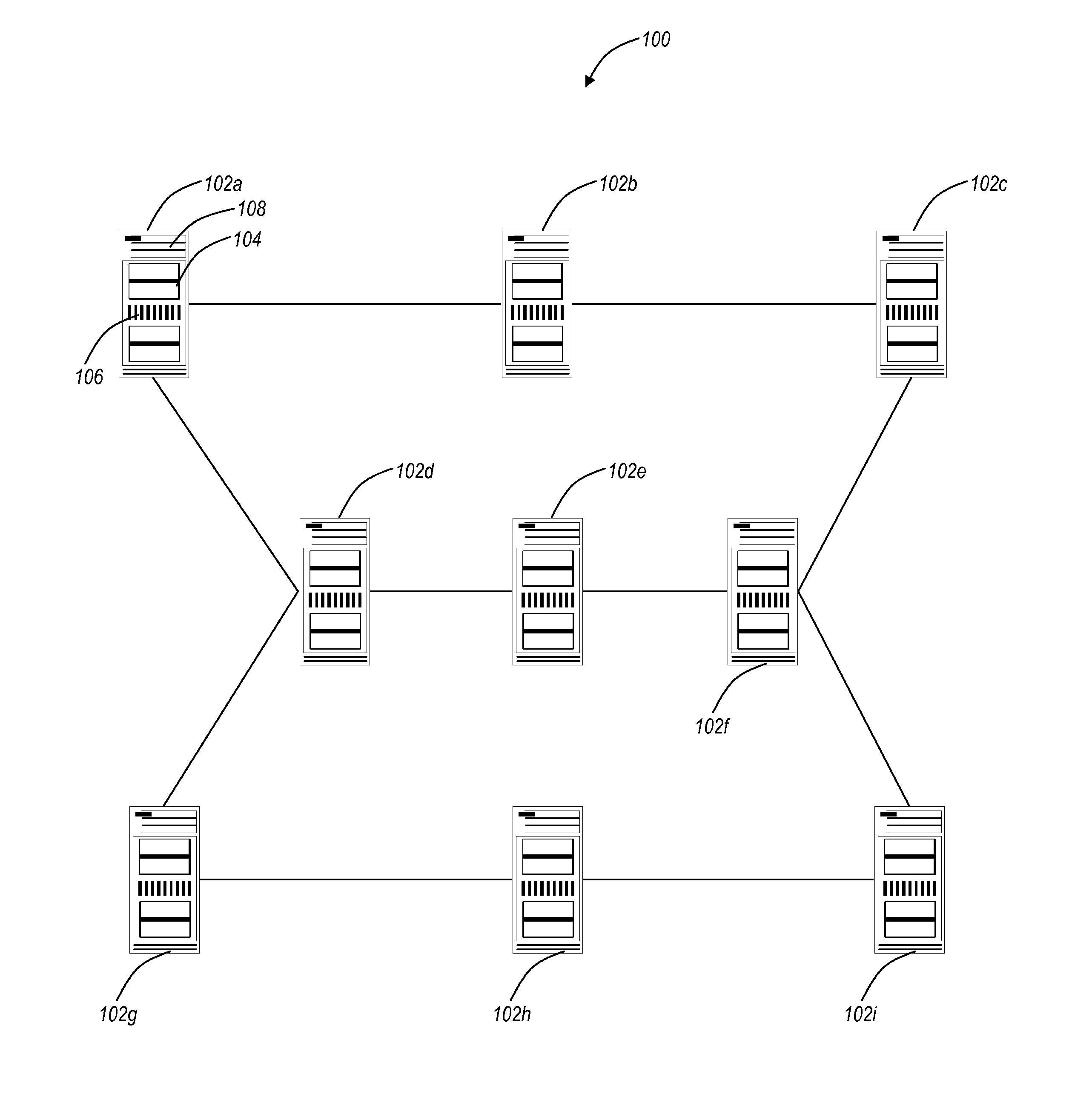
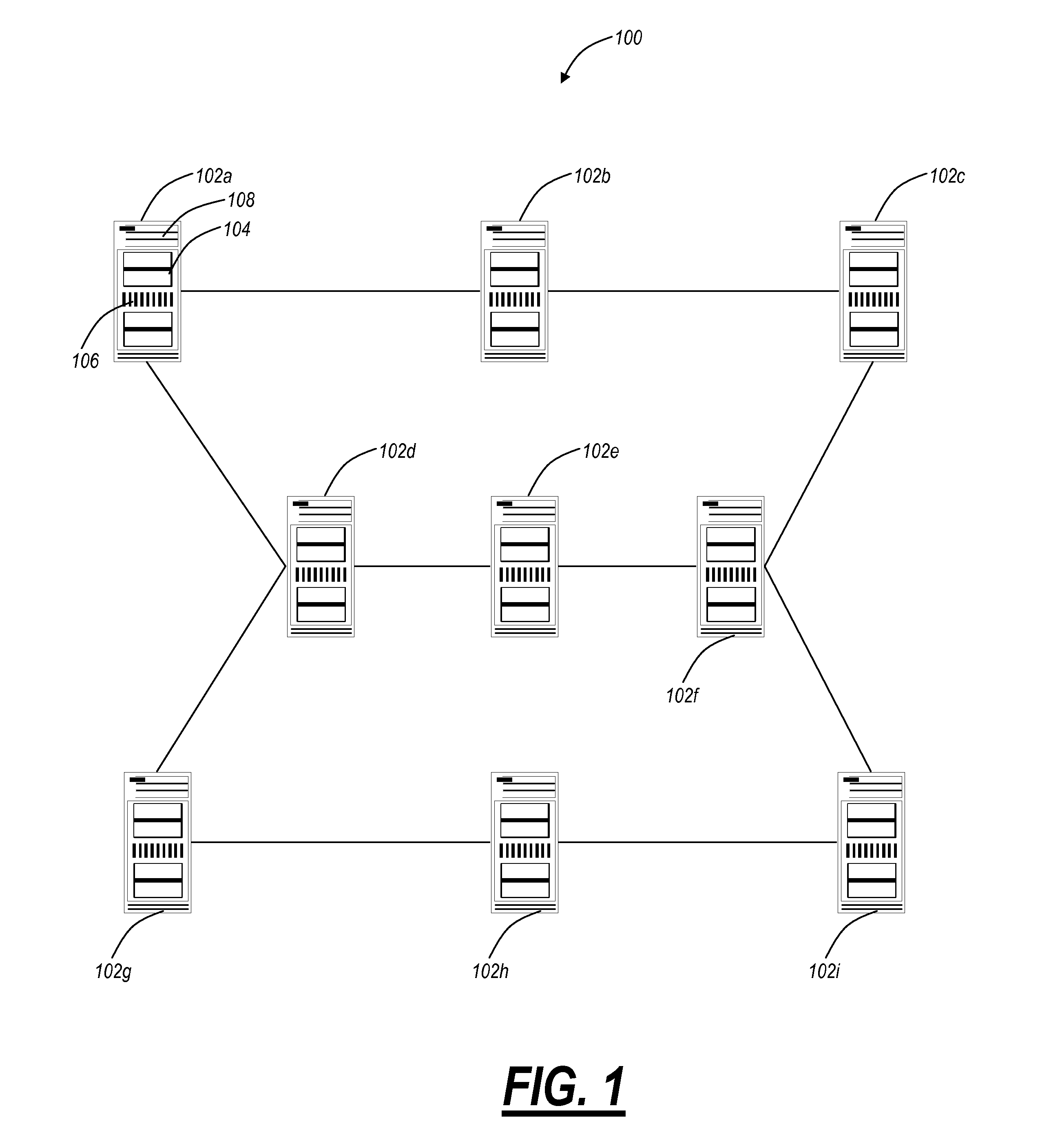
[0012]In various exemplary embodiments, the present invention relates a network, a network element, a system, and a method providing an efficient allocation of protection capacity for network connections and / or services. These may be for services within a given Virtual Private Network (VPN) or Virtual Machine (VM) instance flow. Alternatively, this may be across all VPNs or VM instance flows in the network. Network ingress / egress ports are designed to be VM instance aware while transit ports may or may not be depending on network element capability or configuration. A centralized policy management and a distributed control plane are used to discover and allocate resources to and among the VPNs or VM instances. Algorithms for efficient allocation and release of protection capacity may be coordinated between the centralized policy management and the embedded control plane protocols. Additional coupling of service attributes such as latency may provide more sophisticated path selection...


PUM


Abstract

The present disclosure relates a network, a network element, a system, and a method providing an efficient allocation of protection capacity for network connections and / or services. These may be for services within a given Virtual Private Network (VPN) or Virtual Machine (VM) instance flow. Network ingress / egress ports are designed to be VM instance aware while transit ports may or may not be depending on network element capability or configuration. A centralized policy management and a distributed control plane are used to discover and allocate resources to and among the VPNs or VM instances. Algorithms for efficient allocation and release of protection capacity may be coordinated between the centralized policy management and the distributed control plane. Additional coupling of attributes such as latency may provide more sophisticated path selection algorithms including efficient sharing of protection capacity.

Description

FIELD OF THE INVENTION[0001]The present invention relates generally to communication networks. More particularly, the present invention relates a network, a network element, a system, and a method providing an efficient allocation of protection capacity for network connections and / or services through virtualized shared protection capacity.BACKGROUND OF THE INVENTION[0002]Conventional optical network protection models allow dedicated protection capacity such as 1+1 or shared protection capacity such as bi-directional line switched rings (BLSR), multiplex section-shared protection ring (MS-SPRING) and shared mesh restoration. Protection capacity when dedicated is allocated to a specific customer service instance. Sharing of protection capacity reduces network capacity relative to dedicated protection capacity. Protection capacity may also be designed for single or multiple simultaneous failures. It is further possible to separate the protection capacity resources from the working capa...

Claims


Application Information

Patent Timeline
IPC IPC(8): H04L12/56H04L12/28H04L69/40
CPCH04L49/354H04L49/70
Inventor RANGANATHAN, RAGHURAMANBLAIR, LOUDONGAZIER, MICHAELTHIAGARAJAN, SASHISEKARAN
Owner CIENA
Features
  • Generate Ideas
  • Intellectual Property
  • Life Sciences
  • Materials
  • Tech Scout
  • Unparalleled Data Quality
  • Higher Quality Content
  • 60% Fewer Hallucinations
Learn More