
Radiographic imaging apparatus, method and program

Active Publication Date: 2012-01-19
FUJIFILM CORP
View PDF9 Cites 18 Cited by
  • Summary
  • Abstract
  • Description
  • Claims
  • Application Information

AI Technical Summary

Benefits of technology

[0015]In view of the above-described circumstances, the present invention is directed to providing accurate alignment of images when a plurality of images are obtained with a plurality of radiation source positions, such as in tomosynthesis imaging.

Problems solved by technology

This technique, however, has difficulty in accurately moving the X-ray tube to the calculated radiation source positions due to influences of vibration during imaging, mechanical misalignment, etc., and therefore the radiation source positions during imaging are displaced from the calculated radiation source positions.
Due to this displacement, it is impossible to achieve accurate alignment of projection positions of the object, resulting in degradation of image quality of the tomographic images.
Although accurate positional information of the markers can be obtained by fixing the markers to a fixture, such a fixture is large to some extent, and thus is not suitable for imaging various subjects.
Further, use of a marker fixture limits positions of the markers, and therefore, in the case where a radiation field aperture is used during imaging, it may be impossible to position the markers within the radiation field.
Therefore, accurate alignment cannot be achieved when the radiation source positions for obtaining the images are not on a movement path that is parallel to the detection plane of the detector.

Method used


Image

  • Radiographic imaging apparatus, method and program
  • Radiographic imaging apparatus, method and program
  • Radiographic imaging apparatus, method and program

Examples


Embodiment Construction

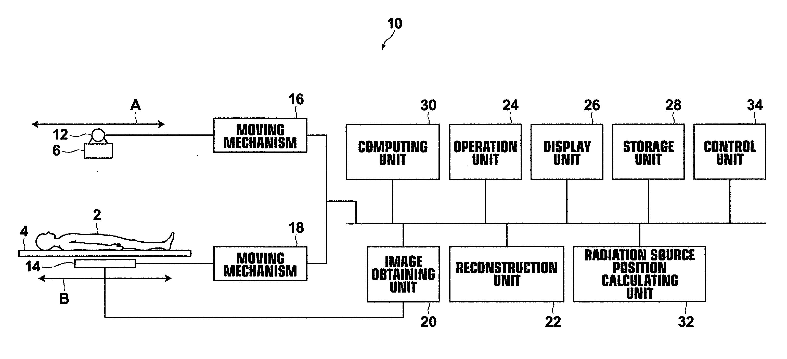
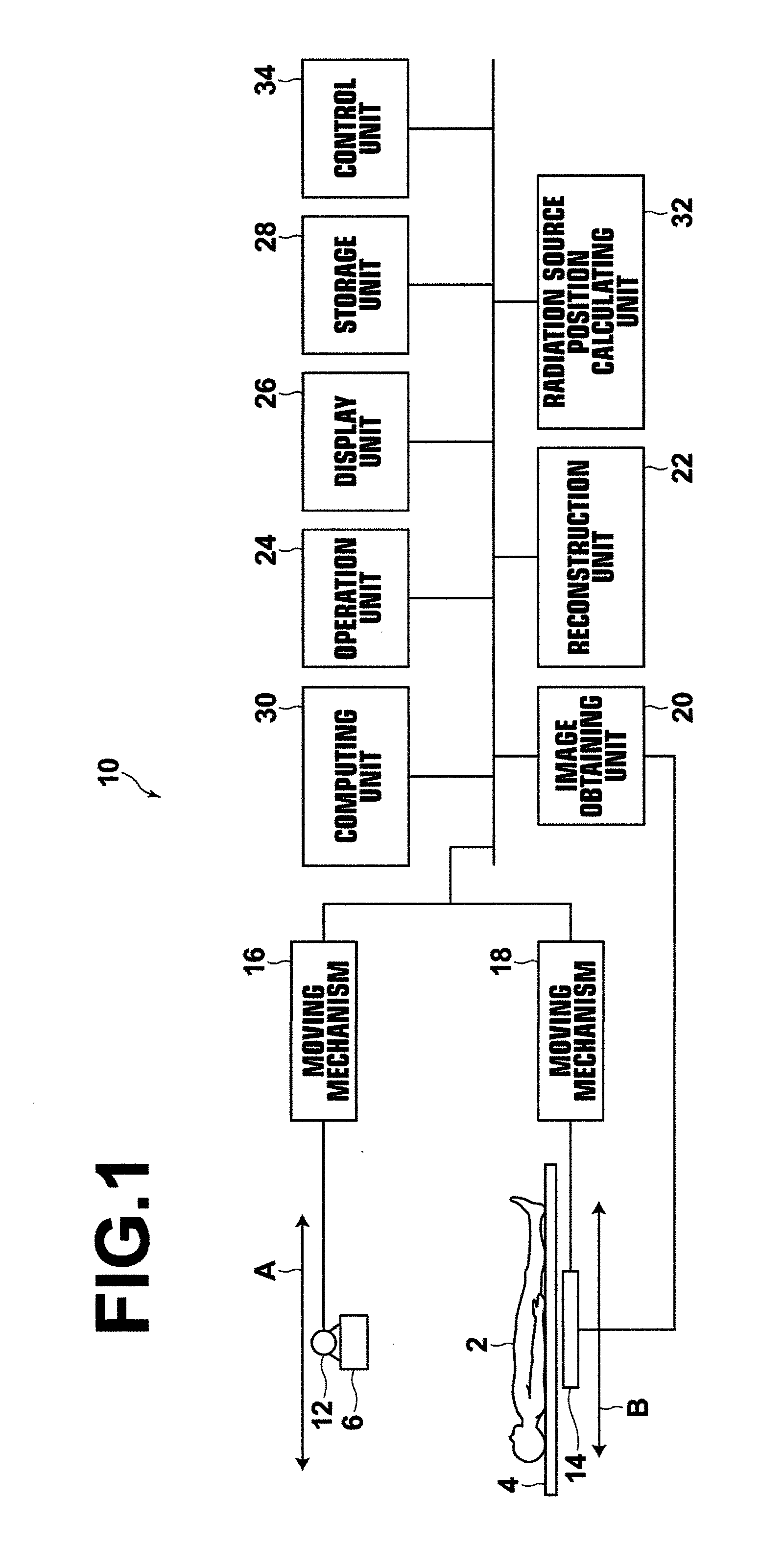
[0038]Hereinafter, embodiments of the present invention will be described with reference to the drawings. FIG. 1 is a schematic diagram illustrating an X-ray imaging apparatus, to which a radiographic imaging apparatus according to a first embodiment of the invention is applied. As shown in FIG. 1, the X-ray imaging apparatus 10 according to the first embodiment is used to perform tomosynthesis imaging, and includes an X-ray tube 12 and a flat panel X-ray detector (which will hereinafter be referred simply to as “detector”) 14. The X-ray tube 12 is moved by a moving mechanism 16 along a straight line or a circular arc, and applies an X-ray from a plurality of positions along the movement path to a subject 2 on an imaging table top 4. In this embodiment, the X-ray tube 12 is moved in the direction of arrow A along a straight line. The X-ray dose applied to the subject 2 is controlled by a control unit, which will be described later, to be a predetermined dose.

[0039]Further, a collima...


PUM


Abstract

A radiographic imaging apparatus includes: a radiation source for applying radiation to a subject and at least one marker; a detecting unit for detecting the radiation transmitted through the subject; and an image obtaining unit for moving the radiation source relative to the detecting means, applying the radiation to the subject from a plurality of radiation source positions provided by the movement of the radiation source, and obtaining a plurality of images corresponding respectively to the radiation source positions. The apparatus further includes a radiation source position obtaining unit for obtaining positional information of each radiation source position of interest relative to a reference radiation source position among the radiation source positions based on at least one marker image contained in each of a reference image obtained with the reference radiation source position and an image of interest obtained with the radiation source position of interest.

Description

BACKGROUND OF THE INVENTION[0001]1. Field of the Invention[0002]The present invention relates to radiographic imaging apparatus, method and program for obtaining a plurality of images at a plurality of radiation source positions, to achieve, for example, tomosynthesis imaging to generate tomographic images.[0003]2. Description of the Related Art[0004]In recent years, tomosynthesis imaging has been proposed with respect to X-ray imaging apparatuses to more closely observe an affected part of the body. In the tomosynthesis imaging, imaging operations are carried out by applying the X-ray to a subject from different angles with moving the X-ray tube, and the thus obtained images are added up to provide an image in which a desired slice is emphasized. In the tomosynthesis imaging, the X-ray tube may be moved in parallel with the X-ray detector or may be moved in a circular or ellipsoidal arc, depending on characteristics of the imaging apparatus and necessary tomographic images, to obta...

Claims


Application Information

Patent Timeline
IPC IPC(8): A61B6/03
CPCA61B6/025A61B6/587A61B6/583A61B6/547
Inventor AKAHORI, SADATO
Owner FUJIFILM CORP
Features
  • Generate Ideas
  • Intellectual Property
  • Life Sciences
  • Materials
  • Tech Scout
  • Unparalleled Data Quality
  • Higher Quality Content
  • 60% Fewer Hallucinations
Learn More