Electrical connector

a technology of electrical connectors and connectors, applied in the direction of coupling device details, coupling device connections, electric discharge lamps, etc., can solve the problems of inconvenient use, inability to allow bidirectional insertion and connection, and bottlenecks

Active Publication Date: 2012-01-19
KIWI CONNECTION LLC
View PDF49 Cites 68 Cited by
  • Summary
  • Abstract
  • Description
  • Claims
  • Application Information

AI Technical Summary

Benefits of technology

[0019]The invention further achieves the above-identified objects by providing an electrical connector, into which a male plug may be bidirectionally inserted and connected. The male plug has an insulation base and a metal housing covering the insulation base. A connection space is formed between the metal housing and the insulation base. The electrical connector includes a plastic base, a tongue, a connection slot and two rows of first connection points. The tongue is projectingly disposed at a front end of the plastic base. The connection slot is disposed at the front end of the plastic ba

Problems solved by technology

The user usually randomly inserts the plug into the socket, so the possibility of failing to insert the plug is equal to ½. So, the user usually has to insert the plug twice, and the inconvenience in use is caused.
The conventional USB socket, either the USB 2.0 or 3.0 socket only has the contact pattern formed on one single surface, and thus cannot allow the bidirectional insertion and connection.
However, if t

Method used


Image

  • Electrical connector
  • Electrical connector
  • Electrical connector

Examples


first embodiment

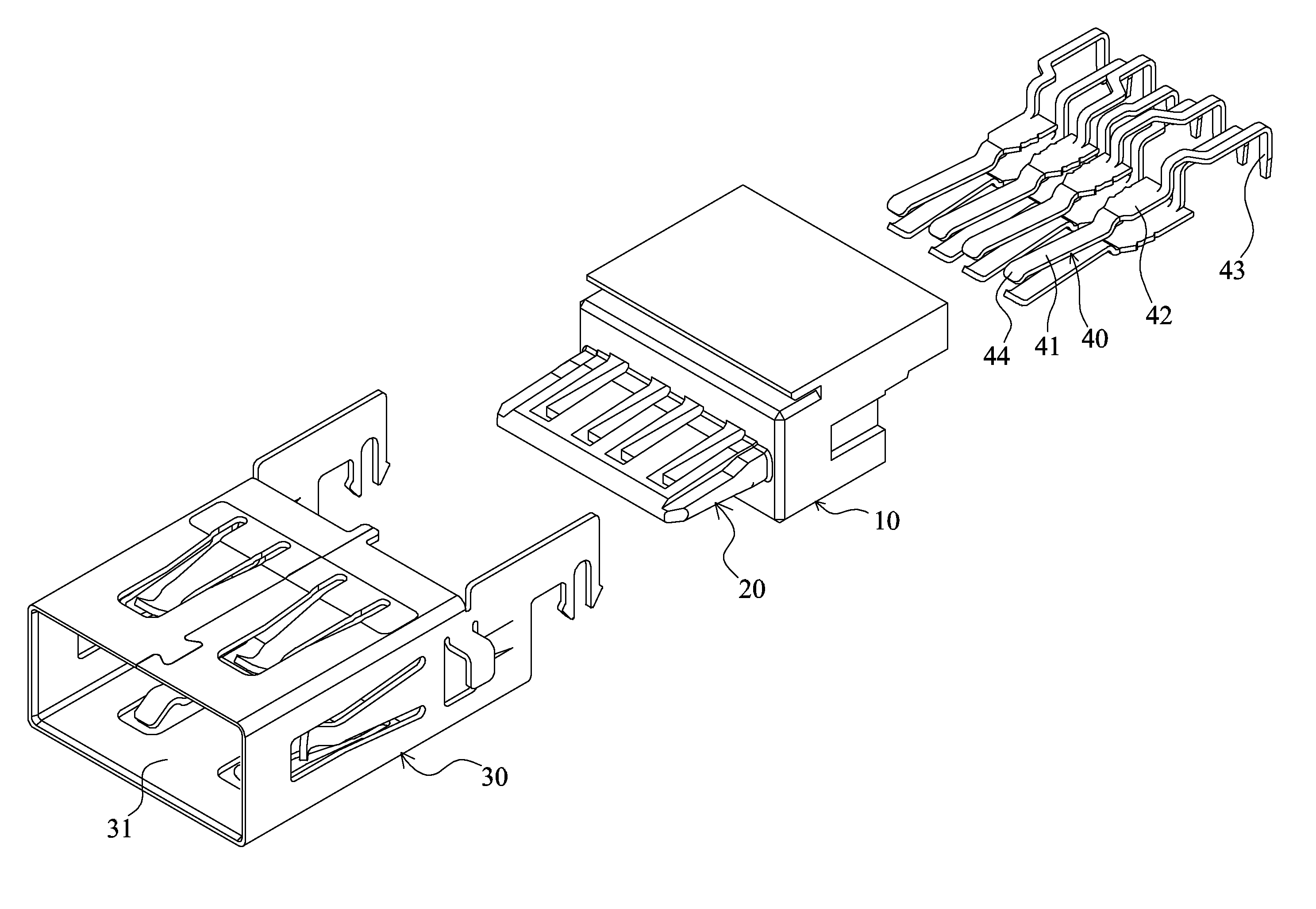
[0075]Referring to FIGS. 3 to 5, the invention is a USB 2.0 socket, which may be connected to the USB 2.0 male plug 90 and includes a plastic base 10, a tongue 20, a metal casing 30 and two rows of first terminals 40.

[0076]The tongue 20 integrally projects beyond the front end of the plastic base 10, and has a thinner front end and a thicker rear end so that it is tapered from rear to front. Thus, the tongue 20 is stronger and cannot be easily broken.

[0077]The metal casing 30 is formed with a connection slot 31. The metal casing 30 is disposed at the front end of the plastic base 10 and covers the tongue 20 therein. The top surface and the bottom surface of the rear section of the connection slot 31 are formed with concave surfaces 32, so that the height of the rear section of the connection slot 31 is greater than that of the insert port. The front end of the connection slot 31 is formed with a guide-in inclined surface 36.

[0078]Each row of first terminals 40 has four terminals. Th...

eleventh embodiment

[0097]As shown in FIGS. 21 to 23, the invention is a USB 3.0 socket, which may be electrically connected to a USB 3.0 male plug and includes a plastic base 10, a tongue 20, a metal casing 30 and two rows of first terminals 40.

[0098]The front end of the plastic base 10 is integrally formed with a frontwardly projecting tab 18, a transversal fitting hole 19 is formed in the tab 18, and a lower cover 17 covers the bottom of the plastic base 10.

[0099]As shown in FIG. 23, the rear section of the tongue 20 is the tab 18 integrally formed with the plastic base, and the front section of the tongue 20 is a circuit board 210. The tab 18 is thicker than the circuit board 210, so the front sections of the two surfaces of the tongue 20 are the thinner and lower concave surfaces 26, and the rear sections of the two surfaces of the tongue are the thicker and higher convex surfaces 27. A step is formed between the concave surface 26 and the convex surface 27 so that the cross-sectional side view of...

ninth embodiment

[0139]As shown in FIG. 49, the 28th embodiment of the invention is almost the same as the ninth embodiment, wherein a front end of the first connection point 44 of the elastic arm 41 of the first terminal 40 of this embodiment is formed with a guiding inclined surface 45 having a narrower plate surface, the first connection points 44 of the two rows of first terminals correspond to each other in a vertical direction, and the guiding inclined surfaces 45 of the elastic arms 41 of the two rows of first terminals 40 are staggered in a left to right direction and suspended without touching the tongue 20. In addition, the metal casing of this embodiment may be similar to that of the seventeenth embodiment.


PUM


Abstract

An electrical connector, into which a male plug, having an insulation base, a metal housing covering the base and a connection space therebetween, may be inserted. The connector includes a plastic base, a tongue, a connection slot and two rows of connection points. The tongue is projectingly disposed at a front end of the plastic base. The slot disposed at the front end of the plastic base covers the tongue. When the plug is inserted and positioned within the slot, the tongue is inserted into the connection space. The connection points are exposed from two surfaces of the tongue. Each connection point is electrically connected to a pin extending out of the plastic base. Spaces of the slot beside the two surfaces of the tongue allow the plug to be bidirectionally inserted and positioned. When the plug is positioned within the slot, the housing does not touch the connection point.

Description

BACKGROUND OF THE INVENTION[0001]1. Field of the Invention[0002]The invention relates to an electrical connector, and more particularly to an electrical connector for bidirectionally electrical connections.[0003]2. Related Art[0004]The universal serial bus (USB) is the most popular signal transmission specification in the modern computer apparatus. The connector socket and the transmission cable satisfying this specification can make the peripheral apparatus, such as a mouse, a keyboard or the like, which is externally connected to the computer, be immediately plugged and played.[0005]At present, the USB 2.0 and USB 3.0 specifications are used. As shown in FIG. 1, the conventional USB 2.0 male plug 90 includes a plastic base 91 and a metal housing 92. The metal housing 92 covers the plastic base 91, and a connection space 93 is formed between the metal housing 92 and the plastic base 91. Only one surface of the plastic base 91 is formed with one row of connection points 94 exposed t...

Claims


Application Information

Patent Timeline
IPC IPC(8): H01R24/00
CPCH01R27/00H01R24/60H01R12/7076H01R13/405H01R2107/00
Inventor TSAI, CHOU HSIEN
Owner KIWI CONNECTION LLC
Why Eureka
Try Eureka