Systems and methods for pedicle screw stabilization of spinal vertebrae

a technology of spinal vertebrae and pedicle screws, which is applied in the field of systems and methods for bone fixation, can solve the problems of loss of natural lordotic curvature, fracture of facet or pars interarticularis (pars), and injuring all 3 columns of vertebrae, and achieves a greater volume and diversity of spaces, and the effect of reducing the risk of fractur

Active Publication Date: 2012-01-19
HUA SHERWIN
View PDF25 Cites 18 Cited by
  • Summary
  • Abstract
  • Description
  • Claims
  • Application Information

AI Technical Summary

Benefits of technology

[0024]Embodiments of the present invention are directed towards improving minimally invasive (optionally adaptable for use with the percutaneous or endoscopic approach) TLIF and PLIF approaches and backing up the ALIF, DLIF, and XLIF approaches. TLIF provides several advantages including: (i) stabilization of both the anterior and posterior portions of the spine through one or more posterior incision(s); (ii) the ability to fill with bone graft material a greater volume and diversity of spaces (front disc space with the spacer, amongst the screws and rods on the sides, and in the back of vertebrae) increasing the chances of a successful stabilization through the development and solidification of bone; (iii) the spacer placed within the front disc space maintains the natural interbody disc height to reduce pressure on nerve roots (from bone spurs, thickened, ligaments, etc.); and (iv) enhanced safety because the spinal canal is accessed from one side only and this reduces the risk of pinching, stretching, or otherwise agitating the spinal nerves.

Problems solved by technology

Fractures are often compressive in nature and typically lead to a pathological curving of the spine resulting in a loss of the natural lordotic curvature in the lumbar and cervical spine, known as kyphosis.
These forces result in fractures of the facet or pars interarticularis (pars).
If the external forces are large enough, vertebrae can collapse resulting in a burst fracture that can injure all 3 columns of the vertebrae (anterior, middle, and posterior columns).
Many traumatic injuries can heal without surgery, but unstable injuries that pose a risk for neurologic injury and / or pain require stabilization through a procedure such as fusion.
Spondylolisthesis results in misalignment of the spine and increases the risk of a nerve becoming entrapped.
Spondylolisthesis can also aggravate or be accompanied by degeneration of disc or facet joint which can lead to axial back pain.
However, most commonly disc degeneration occurs in combination with nerve compression causing both axial back pain and radicular limb pain.
Degradation of the disc space can distort alignment and alter the biomechanical cushion that the disc affords the adjacent vertebrae.
This degradation alters the forces impacted upon the vertebrae and results in axial back pain.
Anterior procedures require a retroperitoneal dissection and risk injury to the large blood vessels anterior to the lumbar vertebrae.
Also injury to the nerve plexus anterior to the vertebrae can result in sexual dysfunction.
The lateral approach is promising but is limited to the upper and mid lumbar levels (rostral to L5,S1) because of obstruction by the iliac crest.
The posterior interbody approach is more time consuming and typically requires more muscle dissection and retraction.
However, the durability of these systems may be an issue.
Over time the possibility of loosening of the pedicle screws or mechanical failure may increase.
The insertion of the rod through the screw heads and locking of the rod with the screws are the steps that are currently most difficult through a minimal incision.
Thus this process is sometimes tedious and frustrating.
The Sextant™ system and other systems that use towers are hindered by both the number of incisions required and the size of each incision.
The patent describes a situation where the angle of the screws intersect, and the towers may interfere with each other.
Additionally, when two tubes intersect at the cutout as shown in FIG. 22B in the '261 patent, the edges of the cutout of one tube interferes or blocks off the lumen of the other tube, and vice versa.
However, if each screw required a separate tower (or tube) (as in conventional tower / tube systems) in order for multiple screws to exist simultaneously, then the sum cross sectional area of the towers / tubes does not permit a single small incision.
The towers / tubes interfere with each other and get in the way of one another due to their size.
Historically this complex group of patients has had complications with bone-screw fixation due to the nature of the bone and types and projection geometries of the screws used, along with their methods of insertion.
These complications include implant failure, screw loosening and pullout.
With every incision that is made there is at least a small risk of inadvertent injury, including nerve damage, even by a skilled surgeon.
Another step of the procedure commonly causing post-surgical patient discomfort and diminished motor / sensory function is placement of the rods within the screws.

Method used


Image

  • Systems and methods for pedicle screw stabilization of spinal vertebrae
  • Systems and methods for pedicle screw stabilization of spinal vertebrae
  • Systems and methods for pedicle screw stabilization of spinal vertebrae

Examples


Embodiment Construction

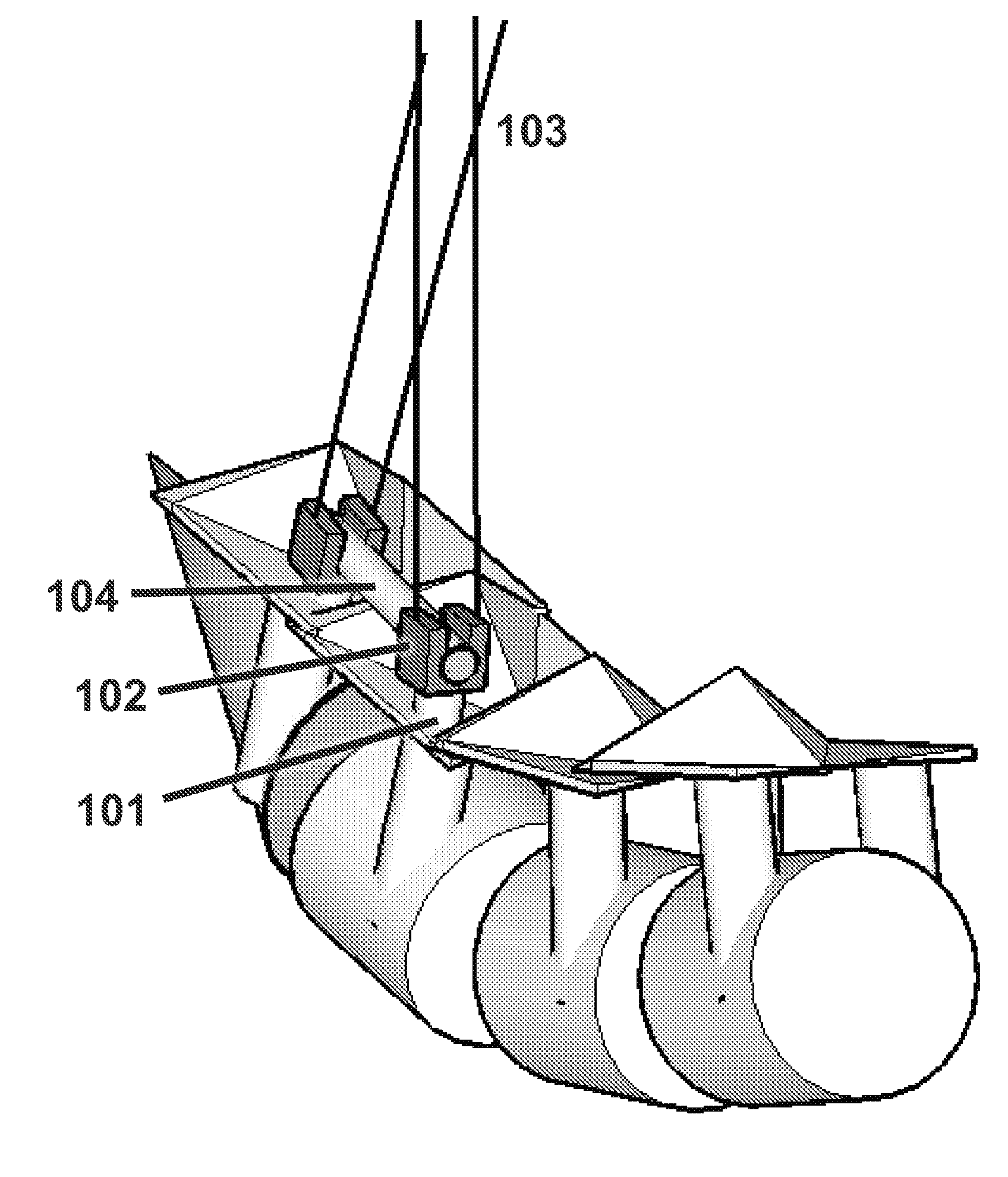
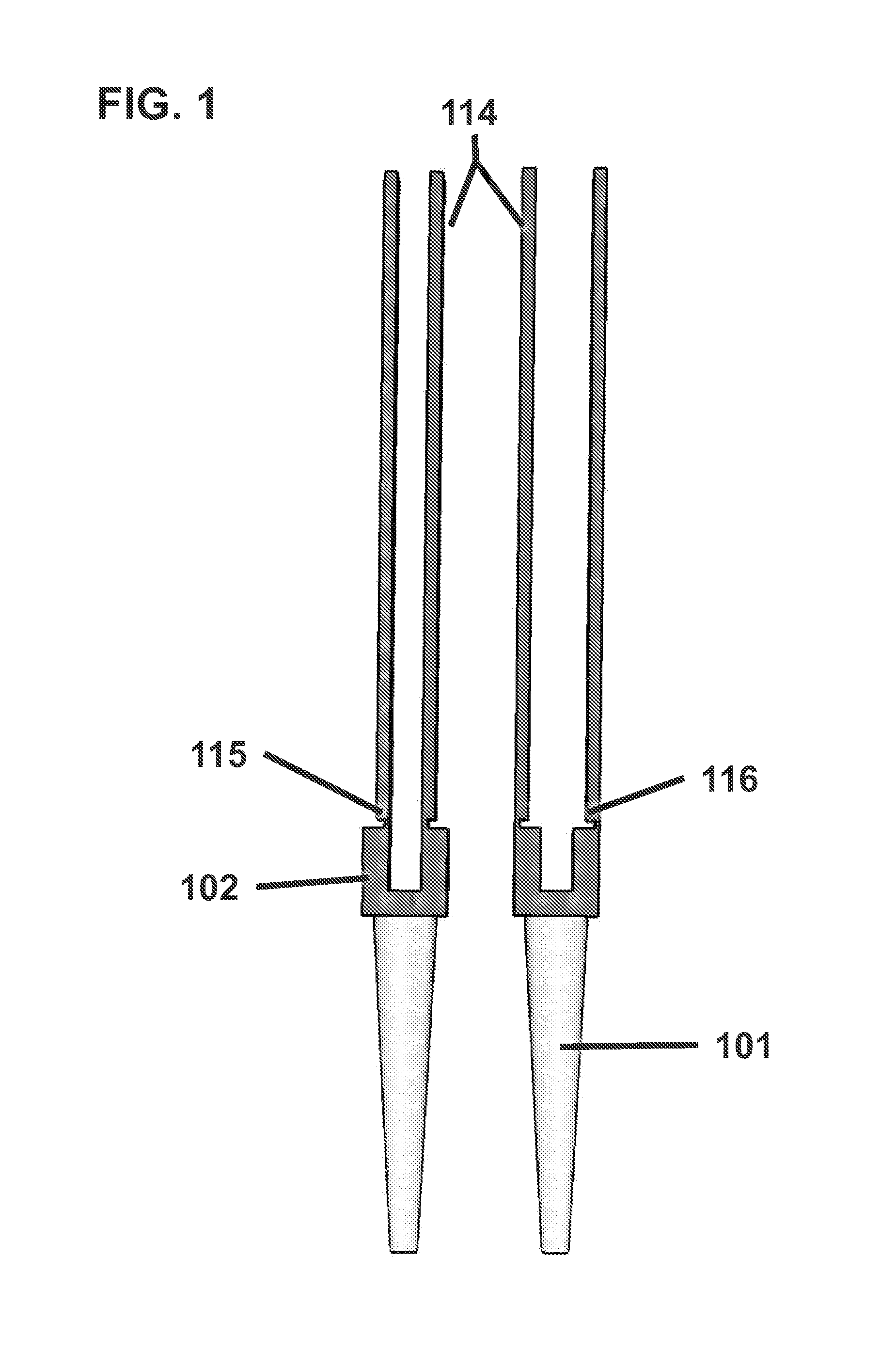
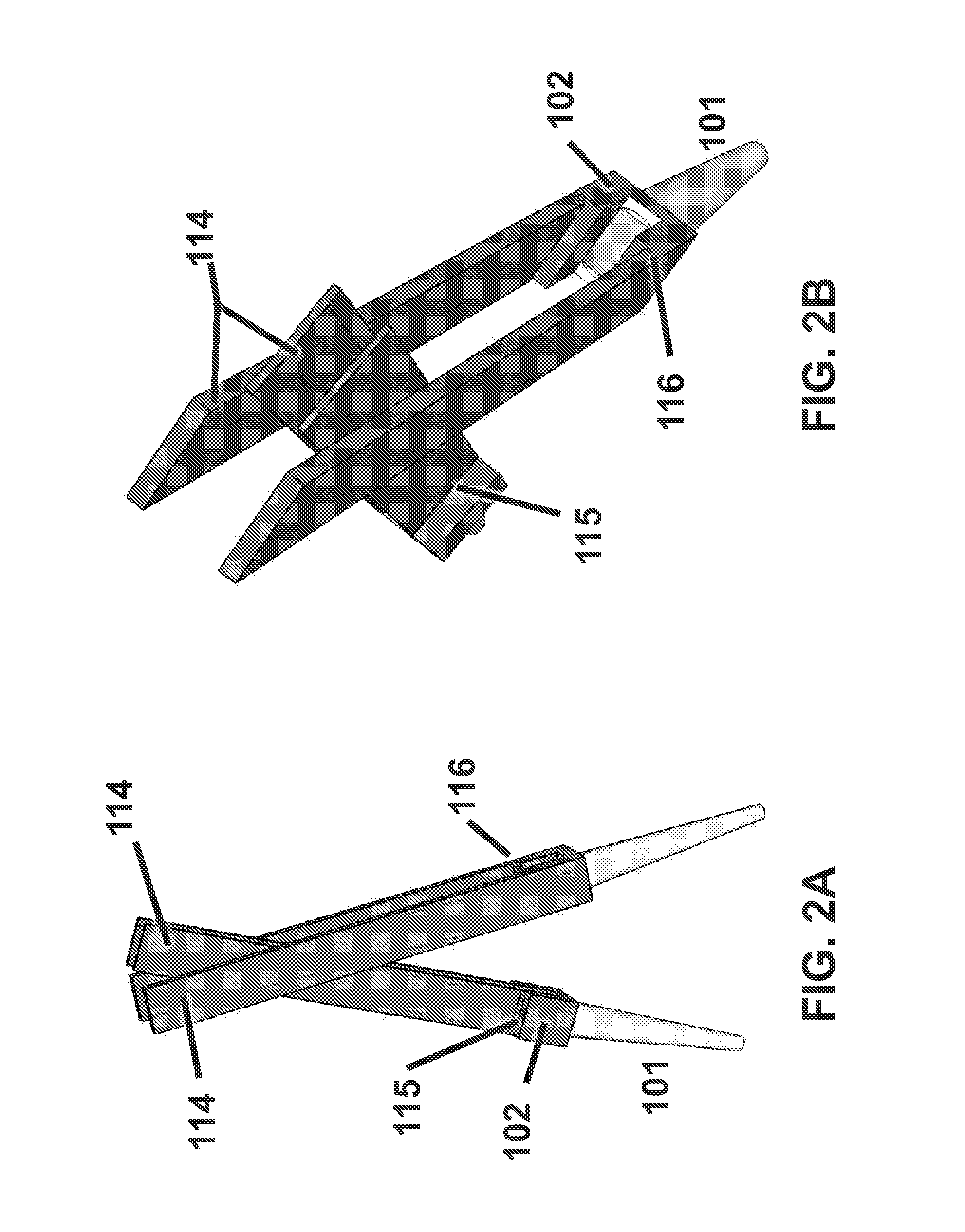
[0103]Embodiments of the invention involve improved systems, apparatuses and methods for guiding one or more screws, rods, and locking assemblies down to the vertebrae and for securing the rod to stabilize the vertebrae. Screws may include pedicle screws as shown in the figures and as described in the patents and publications incorporated by reference herein, and with reference to FIG. 1 may include a threaded bone engaging shaft 101 and a screw head 102. The threaded shaft 101 may be relatively moveable to different angles relative to the screw head 102. For example, a proximal end of the threaded shaft may include a spherical or semi-spherical head that engages a similarly-shaped seat in a lower portion of the screw head 102. The screw head 102 has generally a U-shape, as shown in FIG. 1, defining upwardly extending arms that form a channel for receiving a rod 104. The rod may either sit on the head of the threaded shaft 101, or may sit on an insert placed in the screw head 102 fo...


PUM

PropertyMeasurementUnit
lengthaaaaaaaaaa
lengthaaaaaaaaaa
lengthaaaaaaaaaa

Abstract

The present application is directed to various spinal stabilization systems. The systems can include one or more guiding elements attached to screw members to assist in guiding rod implants and tools to desired locations within a patient. The guiding elements can include a plurality of wires, blades, or tabs. The guiding elements can be capable of criss-crossing or intersecting at or near an incision, such that only a single incision may be needed to perform a surgery. The guiding elements can also include telescoping features that allow the height of the guiding elements to be adjusted in use, thereby allowing multiple telescoping guiding elements to be used with the same incision.

Description

CROSS-REFERENCE TO RELATED APPLICATIONS[0001]This application is a continuation of U.S. Application No. 13 / 082,346, filed Apr. 7, 2011, which claims the benefit of U.S. Provisional Application No. 61 / 469,764, filed Mar. 30, 2011; U.S. Application No. 13 / 082,346 is also a continuation-in-part of International Application No. PCT / US2011 / 030612, filed Mar. 30, 2011, which claims priority to International Application No. PCT / US2010 / 029199, filed Mar. 30, 2010; U.S. Application No. 13 / 082,346 is also a continuation-in-part of International Application No. PCT / US2010 / 029199, filed Mar. 30, 2010, which claims priority to International Application No. PCT / US2009 / 059004, filed Sep. 30, 2009; U.S. Application No. 13 / 082,346 is also a continuation-in-part of U.S. Application No. 13 / 122,388, filed Apr. 1, 2011, which is the U.S. national phase of International Application No. PCT / US2009 / 059004, filed Sep. 30, 2009, published as WO 2010 / 039817 A2, WO 2010 / 039817 A3 and WO 2010 / 039817 A4, which c...

Claims


Application Information

Patent Timeline
Patent Type & Authority Applications(United States)
IPC IPC(8): A61B17/70B23P11/00A61B17/86
CPCA61B17/7001A61B17/7002A61B17/7083Y10T29/49826H04N5/46H04N21/4263H04N21/482A61B17/7091A61B17/7085A61B17/8897A61B17/7032A61B2090/037A61B17/70A61B17/86
Inventor HUA, SHERWIN
Owner HUA SHERWIN
Why Eureka
Try Eureka