System and method for wire-guided pedicle screw stabilization of spinal vertebrae

a technology of pedicle screw and spinal vertebrae, which is applied in the field of system and method of wire-guided pedicle screw stabilization of spinal vertebrae, can solve the problems of tower/tube interference, tower/tube interference, and inability to permit a single small incision, so as to improve the chances of stabilization success, improve the degree of invasiveness, and increase the volume and diversity of spaces

Active Publication Date: 2011-08-11
HUA SHERWIN
View PDF100 Cites 28 Cited by
  • Summary
  • Abstract
  • Description
  • Claims
  • Application Information

AI Technical Summary

Benefits of technology

[0023]The present invention is directed towards improved minimally invasive (optionally adaptable for use with the percutaneous or endoscopic approach) TLIF and PLIF approaches and backing up the ALIF, DLIF, and XLIF approaches. TLIF provides several advantages including: (i) stabilization of both the anterior and posterior portions of the spine through a single posterior incision; (ii) the ability to fill with bone graft material a greater volume and diversity of spaces (front disc space with the spacer, amongst the screws and rods on the sides, and in the back of vertebrae) increasing the chances of a successful stabilization through the development and solidification of bone; (iii) the spacer placed within the front disc space maintains the natural interbody disc height to reduce pressure on nerve roots (from bone spurs, thickened, ligaments, etc.); and (iv) enhanced safety because the spinal canal is accessed from one side only and this reduces the risk of pinching, stretching, or otherwise agitating the spinal nerves.

Problems solved by technology

However, if each screw required a separate tower (or tube) (as in conventional tower / tube systems) in order for multiple screws to exist simultaneously, then the sum cross sectional area of the towers / tubes does not permit a single small incision.
The towers / tubes interfere with each other and get in the way of one another due to their size.

Method used


Image

  • System and method for wire-guided pedicle screw stabilization of spinal vertebrae
  • System and method for wire-guided pedicle screw stabilization of spinal vertebrae
  • System and method for wire-guided pedicle screw stabilization of spinal vertebrae

Examples


Embodiment Construction

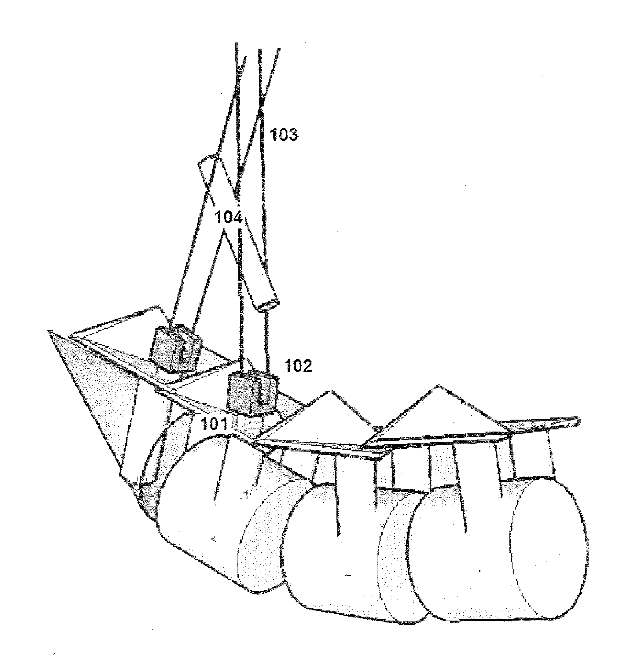
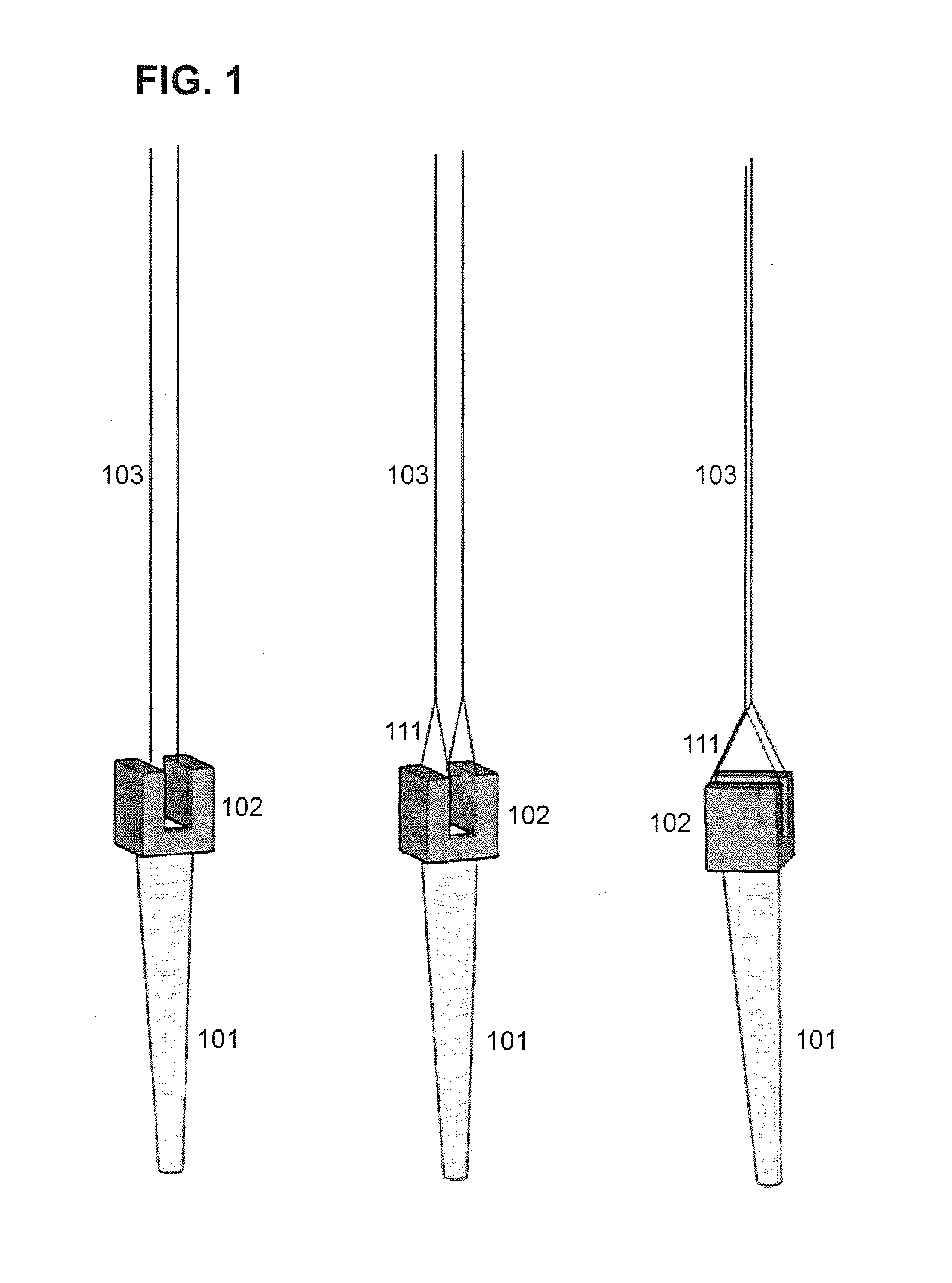
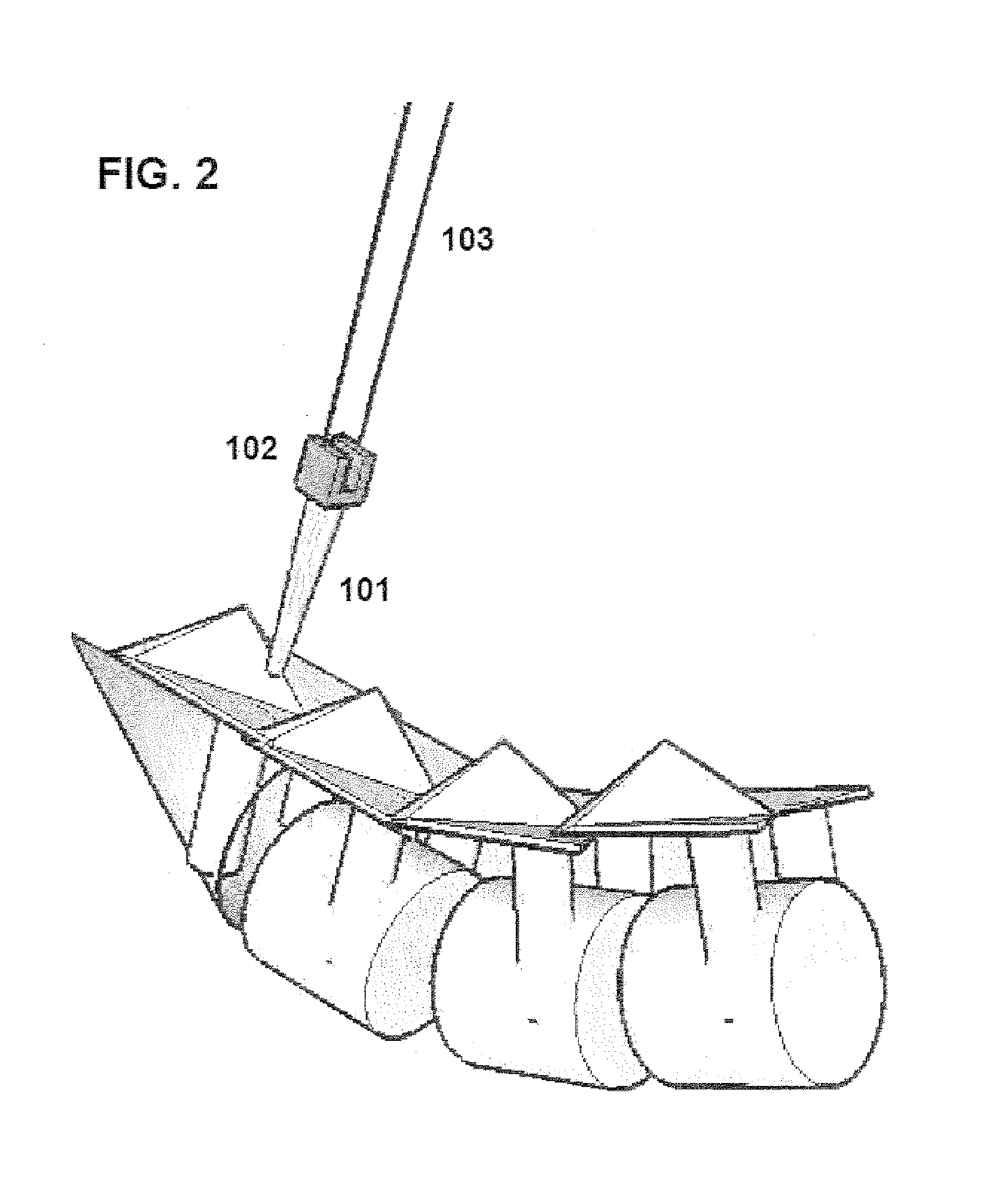
[0054]The invention involves at least a screw, a rod, and a locking assembly being wire-guided down to pedicles of the vertebrae and the rod secured to stabilize the vertebrae. The locking assembly may be built into the screw head or be a separate element. The locking assembly may be guided down to the screw before or after insertion of the rod depending upon the details of the locking mechanism used to secure the rod. In some cases, the locking assembly is already present on the screw head before the rod is received and in other cases the rod is inserted into the screw head first and the locking assembly follows.

[0055]A preferred embodiment of the present inventive system and method is to use one wire 103 on each side of a screw head 102 such that there are two wires 103 per screw shaft 101 to securely trap a rod 104 over the screw shaft 101 within the screw head 102. This embodiment is believed to provide the most rod 104 stability for the least volume of stabilizing elements (the...


PUM


Abstract

An improved system and method for positioning screws and rods to immobilize bones is provided. Specifically, the system and method is optimal for performing transforaminal lumbar interbody fusion (TLIF) and other interbody fusions in the spine. The system involves pedicle screws detachably connected to wires that guide rods down to the screws. The wires are strong, narrow, flexible, adjustable in tension, and easily disconnected from the screws after rod placement via a process such as cutting, radiating, burning, dissolving, etc. The use of wires to place the rods avoids the conventional bulky tower apparatuses of the prior art while at the same time enhancing the accuracy of placement. One of the preferred methods involves relying upon the natural lordotic curvature of the spine and the narrow diameter of the wires to insert many elements through a single minimally invasive incision.

Description

BACKGROUND OF THE INVENTION[0001]1. Field of the Invention[0002]The present invention relates to medical devices, systems and methods for bone fixation. Specifically, the invention is directed to stabilize adjoining vertebrae in the cervical, thoracic, and lumbosacral spine. More specifically, the invention is directed to fusion or stabilization of vertebrae in the lumbar spine to alleviate axial back pain. Most specifically, the invention is directed to improving minimally invasive surgical (MIS) approaches to pedicle screw fusion by reducing the number and size of incisions and the size of the medical instruments inserted therein.[0003]2. Description of the Related Art[0004]While some lower back conditions can be ameliorated with non-surgical approaches, spinal fusion is recommended for certain conditions when non-surgical approaches fail. Non-surgical: approaches include medications, physical therapy, chiropractic treatment, traction, epidural steroid injections, facet blocks or ...

Claims


Application Information

Patent Timeline
Patent Type & Authority Applications(United States)
IPC IPC(8): A61B17/88
CPCA61B17/7001A61B17/7002A61B17/701A61B17/7053A61B17/7083A61B2019/5466A61B2019/444A61B2019/542A61B2019/5437A61B2019/5441A61B2019/5454A61B17/8863A61B2090/392A61B90/92A61B2090/3937A61B2090/3941A61B2090/3954A61B2090/3966A61B17/70A61B17/86A61L27/14
Inventor HUA, SHERWIN
Owner HUA SHERWIN
Why Eureka
Try Eureka