Safety controller and method for controlling an automated installation

a safety controller and automated installation technology, applied in the direction of automatic controllers, programme control, total factory control, etc., can solve the problems of considerable complexity in development and manufacture, human or material goods hazards, and the diagnosis report presented on the display unit does not correctly reproduce reality

Active Publication Date: 2012-01-19
PILZ (COMPANY)
View PDF23 Cites 16 Cited by
  • Summary
  • Abstract
  • Description
  • Claims
  • Application Information

AI Technical Summary

Benefits of technology

[0015]It is therefore an object of the present invention to provide a safety controller and a method offering better information to operating personnel about faults which might occur during operation of the system, and to give them better support for rectifying these faults.

Problems solved by technology

Such sensors are used in order to safeguard a machine, for example, which presents a hazard to humans or material goods during operation.
Extremely high demands are therefore put on safety controllers in terms of their own failsafety, which results in considerable complexity for development and manufacture.
Hence, the display unit is used to present a logical error.
In this case, the determined installation state, i.e. the determined logical error, is not based on reality and the diagnosis report presented on the display unit does not correctly reproduce reality.
This may be the case, by way of example, when the filling level sensor is faulty or there is an error in the wiring connecting the filling level sensor to the safety controller, or an error in the safety controller itself.
The above thoughts show that the diagnosis measures used in the known safety controllers and methods are still not optimal.

Method used


Image

  • Safety controller and method for controlling an automated installation
  • Safety controller and method for controlling an automated installation
  • Safety controller and method for controlling an automated installation

Examples


Embodiment Construction

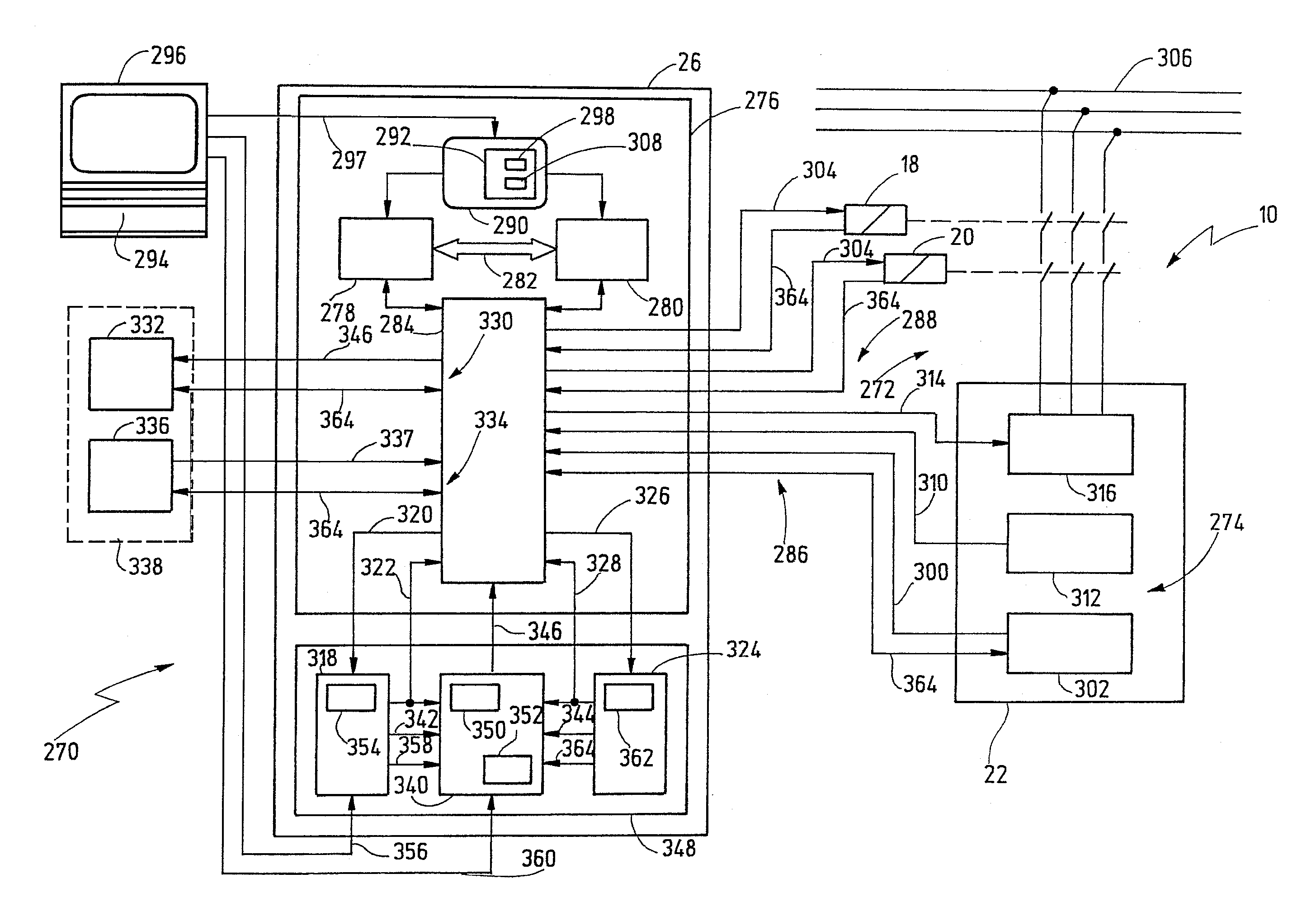
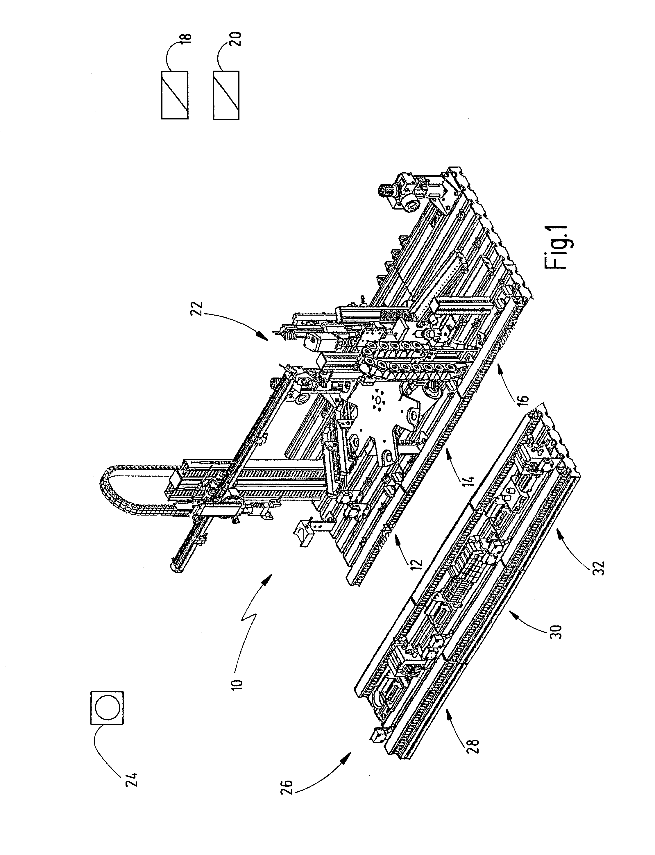
[0090]In FIG. 1, an installation to be controlled is denoted as a whole by the reference numeral 10. The installation 10 comprises three components, namely a handling station 12, a process station 14 and a test station 16, and two contactors 18, 20. The handling station 12 is used to fill the process station 14 with workpieces. These workpieces are machined in the process station 14. Next, the machined workpieces are forwarded by the handling station 12 to the test station 16, in which a check is performed to determine whether the machined workpiece satisfies appropriate examination criteria. If these examinations are passed, the process station 14 can again be filled with a new workpiece for machining. The two contactors 18, 20 connect the loads 22 in the system 10 to a power supply—not shown. The system has an associated first emergency-off pushbutton 24 which can be used to disconnect the system 10 and in so doing transfer it to a safe state in the event of a hazard. To this end,...


PUM


Abstract

A safety controller for controlling an automated installation in accordance with a user program has a control unit receiving a plurality of control input signals from a plurality of sensors. The control unit produces a plurality of control output signals on the basis of the control input signals in accordance with a user program. The control output signals drive actuators in order to adopt one of a plurality of installation states of the automated installation. An installation diagnosis evaluation unit produces a number of installation state signals representing which one of the plurality of installation states is existent at a defined moment of time. In addition, a system diagnosis evaluation unit produces a number of system state signals, with each system state signal representing one from a plurality of operational system states of the controller system, which is formed by the control unit and its connected sensors and actuators, at the defined moment of time. A diagnosis report unit produces a number of diagnosis signals depending on the installation state signals, depending on the system state signals, and depending on predefined associations between said installation states and said operational system states. The diagnosis signals represent a number of diagnosis reports which are a result of a combination of both the installation states and associated operational system states. A display unit displays the diagnosis reports in response to the diagnosis signals.

Description

CROSSREFERENCES TO RELATED APPLICATIONS[0001]This application is a continuation of international patent application PCT / EP2009 / 008265 filed on Nov. 20, 2009 designating the U.S., which international patent application has been published in German language and claims priority from German patent application DE 10 2008 060 005.9 filed on Nov. 25, 2008. The entire contents of these priority applications are incorporated herein by reference.BACKGROUND OF THE INVENTION[0002]The present invention relates to a safety controller and a method for controlling an automated installation, and more particularly to a safety controller and a method providing enhanced diagnosis capabilities.[0003]A safety controller within the meaning of the present invention is an apparatus or an arrangement which receives input signals delivered by sensors and produces output signals therefrom by means of logic combinations and sometimes further signal or data processing steps. The output signals can then be suppli...

Claims


Application Information

Patent Timeline
Patent Type & Authority Applications(United States)
IPC IPC(8): G05B9/02
CPCG05B19/0428G05B2219/23292G05B2219/34465G05B2219/31469G05B2219/31455G05B9/03Y02P90/02
Inventor ZONDLER, MARTINEHRHART, HELMUTFOERSTER, HARALD
Owner PILZ (COMPANY)
Why Eureka
Try Eureka