Enclosed granular fuel burning boiler

a granular fuel and boiler technology, applied in the combustion process, lighting and heating apparatus, combustion types, etc., can solve the problems of affecting the efficiency of the boiler, and achieve the effect of avoiding disturbing the burning of fuel

Active Publication Date: 2012-01-26
ALLEY ENTERPRISES UNLIMITED CO
View PDF4 Cites 6 Cited by
  • Summary
  • Abstract
  • Description
  • Claims
  • Application Information

AI Technical Summary

Benefits of technology

[0036]The number of air inlet holes is varied depending on the heat output requirements of the boiler. This has been found to be a very effective way of varying the heat output of boilers without the necessity to provide different sizes of brazier.
[0037]With the enclosed granular fuel boilers, as described above, a diverter plate is mounted on or adjacent the distal wall of the brazier to direct granular fuel which on delivery into the brazier would fall over the distal wall back into the brazier. The diverter plate is simply an extension of the front of the brazier enclosure. The advantage of this is that when pellets fall out of the brazier they do not fall on to the ash in the ash pan where the heated ash causes them to burn inefficiently giving off carbon monoxide. Again this would not appear to be a major problem but in fact it is a problem which causes considerable difficulties. The householder notices that there is a considerable amount of smoke from the boiler and presume is that it is operating inefficiently, and indeed it is.
[0038]In a further embodiment of the invention an airflow diverter is mounted above each side wall of the brazier. The airflow diverter is provided by a plate projecting from the adjacent side wall and across portion of the brazier base. The advantage of the airflow diverter is to ensure that air is delivered down into the centre of the brazier for efficient combustion.
[0039]In a still further embodiment of the invention there is provided a granular fuel supply tube mounted above the brazier for delivery of fuel under gravity to the brazier and in which flow control means are provided. The advantage of the flow control means is to ensure that the granular fuel, very often wood pellets, is delivered into the brazier as gently as possible. This prevents the wood pellets hopping up against the diverter plate and also avoids disturbing the burning fuel in the brazier.

Problems solved by technology

This does not seem to be a major problem, however, in practice, it is and it is detrimental to the efficiency of the boiler to have large amounts of vitrified clinker in the brazier preventing adequate combustion of the fuel.

Method used


Image

  • Enclosed granular fuel burning boiler
  • Enclosed granular fuel burning boiler
  • Enclosed granular fuel burning boiler

Examples


Embodiment Construction

[0073]Before describing the invention, reference is made to the disclosures of some pending patent applications, which are in the public domain, namely, Irish Patent Application Number 2007 / 0226 filed Mar. 29, 2007, entitled “A Solid Fuel Boiler”, UK Patent Application Number 0821060.1, filed Nov. 18, 2008, entitled “A Granular Fuel-Fired Boiler Brazier” and PCT Patent Application Number PCT / EP2009 / 067898 filed Dec. 23, 2009, entitled “A Dual Fuel Boiler” (Publication No. WO2010 / 072830). The disclosure of the specifications of each of these applications is incorporated herein by way of direct reference.

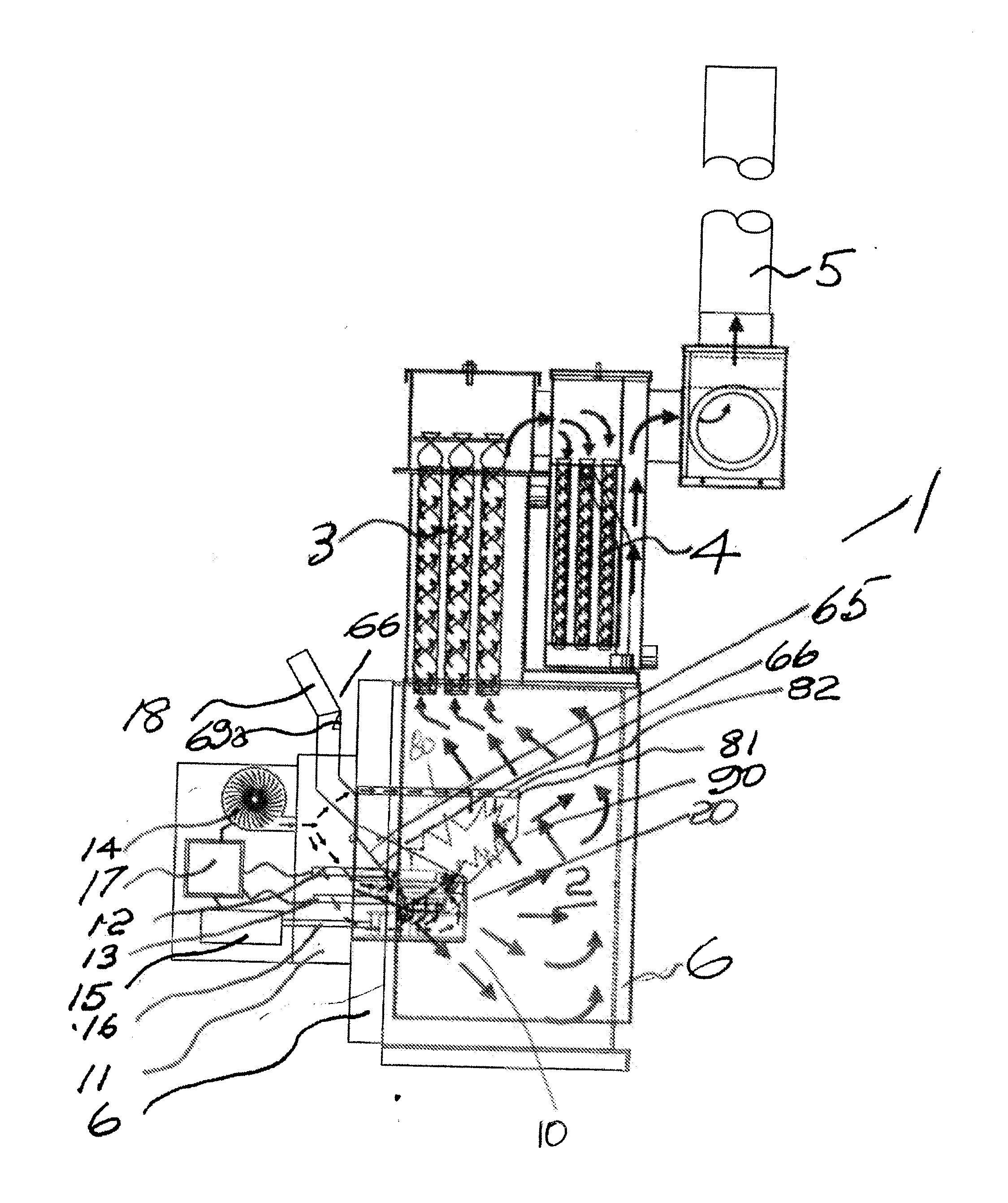
[0074]Referring to the drawings and initially to FIG. 1 thereof, there is illustrated an enclosed granular fuel burning boiler indicated generally by the reference numeral 1 comprising a combustion chamber 2 feeding heat exchangers 3 and condensing tubes 4 which in turn feed a flue 5, all of which have been described in our co-pending UK Patent Application Number 0821060.1 The combust...


PUM


Abstract

There is illustrated a fuel fired brazier for an enclosed granular fuel burning boiler. The brazier has an apertured grate-like brazier base. The brazier base is moved by an actuator from an operative position, retaining fuel in the brazier to a discharge position where ash can fall through a hole. At the same time, fragmentation means, formed by crushing teeth, move across the brazier to trap, for example, a large piece of clinker, between it and the opposed distal wall of the brazier.

Description

CROSS-REFERENCE TO RELATED APPLICATION[0001]This application claims priority from UK Patent Application No. 1010460.2 filed on 22 Jun. 2010, the entire contents of which are herein incorporated by reference.INTRODUCTION[0002]This invention relates to granular fuel burning boilers.[0003]The invention particularly relates to an enclosed granular fuel burning boiler of the type comprising:[0004]a fuel-fired brazier comprising an apertured grate-like brazier base and upstanding side walls, namely a proximal wall, a distal wall and a pair of connecting side walls, and the base being movable from an operative position retaining fuel in the brazier to a discharge position to allow ash contents to fall out of the brazier;[0005]fragmentation means so as to break up any vitrified ash contents in the brazier when the brazier base is moved to the discharge position;[0006]and[0007]a fan for delivering air to the brazier through a plenum chamber.[0008]The terms “distal” and “ proximal” are used i...

Claims


Application Information

Patent Timeline
Patent Type & Authority Applications(United States)
IPC IPC(8): F23B40/04F23L5/02F23H13/06F23B50/04
CPCF23B10/00F23B60/02F23J1/06F23H15/00F23B80/04F23B5/02
Inventor GRANT, STEPHEN WILLIAM JOHN
Owner ALLEY ENTERPRISES UNLIMITED CO
Why Eureka
Try Eureka