
Method of producing a heterostructure with local adaptation of the thermal expansion coefficient

a technology of thermal expansion coefficient and heterostructure, which is applied in the direction of semiconductor devices, semiconductor/solid-state device details, electrical devices, etc., can solve the problems of reducing the quality of the bond between the substrates, and delamination or splitting of the substrates or layers that are present, so as to reduce the strain and/or deformation

Active Publication Date: 2012-01-26
SOITEC SA
View PDF5 Cites 16 Cited by
  • Summary
  • Abstract
  • Description
  • Claims
  • Application Information

AI Technical Summary

Benefits of technology

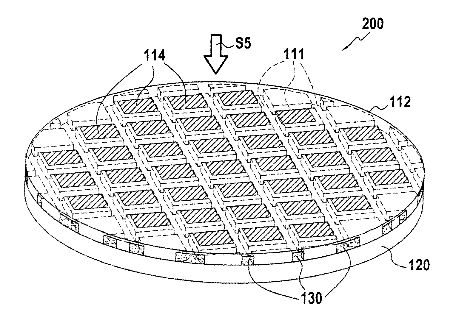
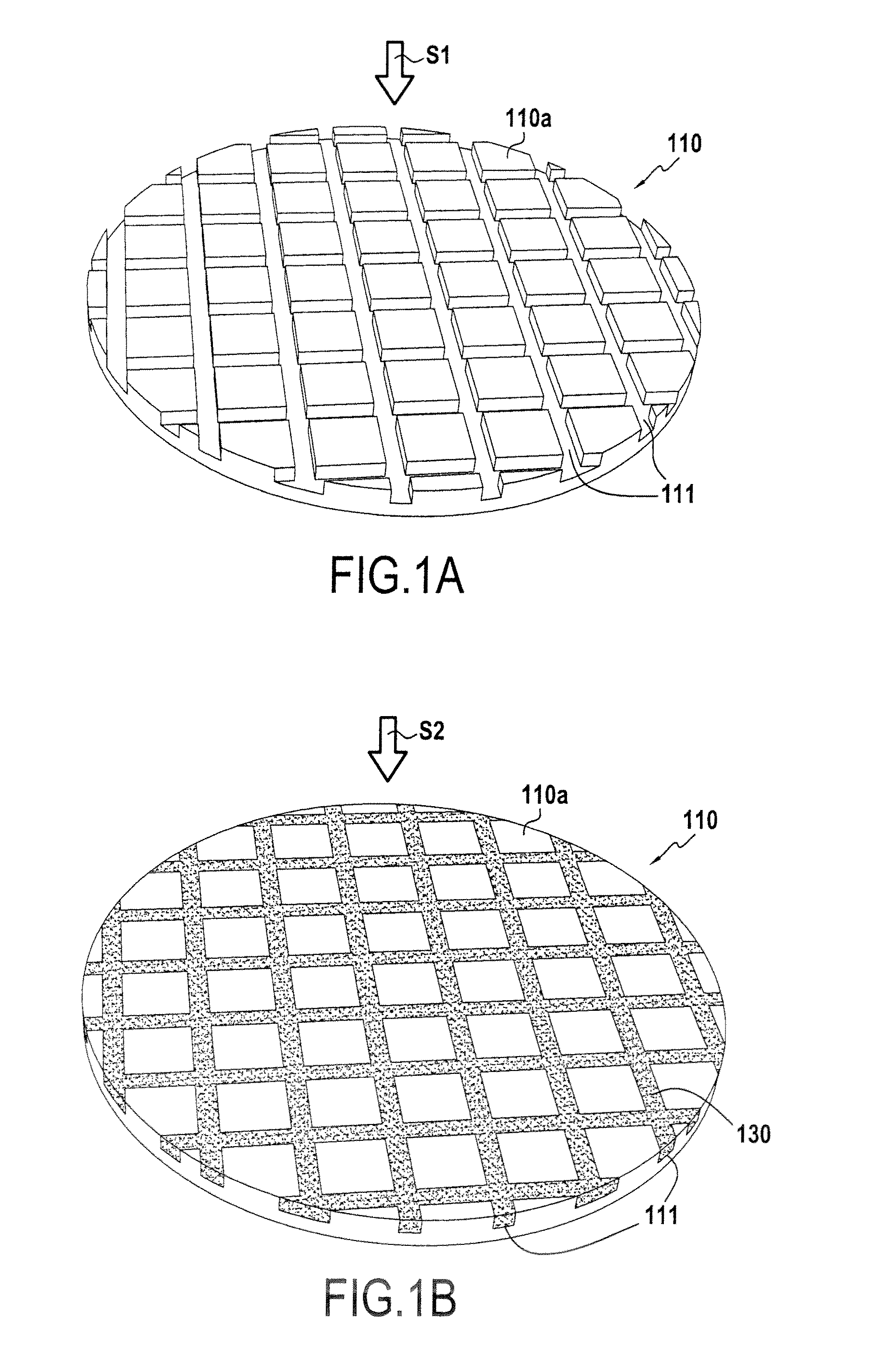
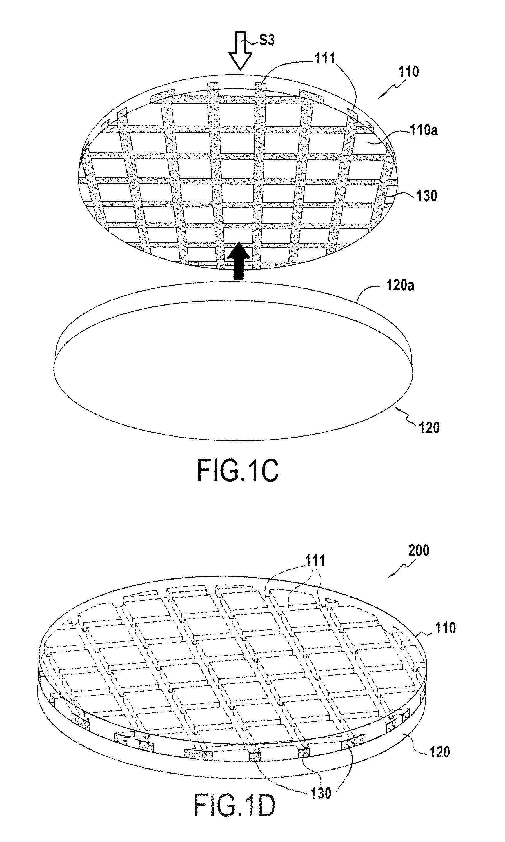
The invention proposes a method of producing a heterostructure that reduces deformations and strains during heat treatments. This is achieved by bonding two substrates with different thermal expansion coefficients and filling the bonding surface of one substrate with a material that matches the thermal expansion coefficient of the other substrate. The resulting structure has better matching thermal expansion coefficients and is less defective during high-temperature heat treatments. The method also allows for the formation of components on the substrates and the separation of components through trenches in the bonding surface. The heterostructure produced using this method has improved performance and reliability.

Problems solved by technology

During rises in temperature, variations in the behavior of one of the two substrates relative to the other generate stresses and / or deformations in the heterostructure that increase the defectivity thereof and reduce the quality of the bond between the substrates.
In general, because of difference in the thermal expansion coefficients, variations in temperature, for example from 200° C. and above, may cause strains, but may also cause delamination or splitting of the substrates or layers that are present, and / or plastic deformations and / or fractures and / or breakage of one or more substrates or layers that are present.
As a consequence, the problem arises of finding a method that can avoid such effects in such a heterostructure during rises in temperature.

Method used


Image

  • Method of producing a heterostructure with local adaptation of the thermal expansion coefficient
  • Method of producing a heterostructure with local adaptation of the thermal expansion coefficient
  • Method of producing a heterostructure with local adaptation of the thermal expansion coefficient

Examples


Embodiment Construction

[0023]The method of the present invention is of general application to the production of heterostructures formed by assembling at least one first substrate with a second substrate, the substrates having different thermal expansion coefficients.

[0024]The method of the invention proposes producing trenches in at least one of the two substrates to be assembled together, the trenches being produced in the bonding face of the substrate and being filled with a material that has a thermal expansion coefficient lying between those of the two substrates.

[0025]Each substrate may be constituted by a mono-layered structure (a single material) that may include motifs and / or components, or a multi-layered structure (stack of layers of different materials). With a multi-layered structure, it is the thermal expansion coefficient of the material of the layer that is closest to the bonding interface that is taken into account in selecting the thermal expansion coefficient of the material filling the ...


PUM

PropertyMeasurementUnit
temperatureaaaaaaaaaa

Abstract

A method of producing a heterostructure by bonding at least one first substrate having a first thermal expansion coefficient onto a second substrate having a second thermal expansion coefficient, with the first thermal expansion coefficient being different from the second thermal expansion coefficient. Prior to bonding, trenches are formed in one of the two substrates from the bonding surface of the substrate. The trenches are filled with a material having a third thermal expansion coefficient lying between the first and second thermal expansion coefficients.

Description

TECHNICAL FIELD AND PRIOR ART[0001]The present invention relates to producing heterogeneous structures formed by bonding at least one first substrate having a first thermal expansion coefficient to a second substrate having a second thermal expansion coefficient that is different from the first thermal expansion coefficient. Said heterostructures are used in microelectronics or in optoelectronics in particular.[0002]When assembling two substrates with different thermal expansion coefficients, for example differing by at least 10% or 20% at ambient temperature (20° C.), or during any subsequent treatment of the two assembled substrates, temperature rise stages may take place, for example to reinforce the bonding interface.[0003]During rises in temperature, variations in the behavior of one of the two substrates relative to the other generate stresses and / or deformations in the heterostructure that increase the defectivity thereof and reduce the quality of the bond between the substra...

Claims


Application Information

Patent Timeline
Patent Type & Authority Applications(United States)
IPC IPC(8): H01L29/06H01L21/30
CPCH01L21/2007H01L21/20
Inventor COLNAT, CYRILLE
Owner SOITEC SA
Learn More