
Bike Having Indicia Insert for Display or Advertising

a technology for indicia and bicycles, applied in the field of bicycles, can solve the problems of limiting the viewable surface area, if no such crossbar is provided or if provided, and small diameter and surface area, and achieve the effect of enhancing minimizing the balance of the fram

Inactive Publication Date: 2012-01-26
MEREDITH JEFFREY OWEN
View PDF5 Cites 11 Cited by
  • Summary
  • Abstract
  • Description
  • Claims
  • Application Information

AI Technical Summary

Benefits of technology

[0019]Indicia including one or a combination of text, color, design, art, and symbols may be imparted to this planar portion, in vertical sizes which can be easily discerned or read by pedestrians and motorists viewing the bicycle from a distance on one side or the other. Since generally bicycles ride in the street or in bike lanes, and third party viewers tend to be on sidewalks or in cars distant from the bicycle, unlike the small print on the surface circumference of the conventional frame tubes, the indicia on the disclosed planar member can be sized sufficiently large to be seen and understood by those distant viewers. Further, in some modes of the device herein, the planar member can be adapted to engage the surrounding tubing or frame members in a fashion to increase the strength of the frame, in addition to providing a large surface area for indicia of increased size from that of the frame. Additionally, the large planar members can be configured for a removable engagement with the frame and be from a kit of a plurality of such planar members having different indicia on each kit member. This allows for easy changing of the indicia, for instance, during the day of a race or event where riders could function as moving information signs with changing information provided by changing the indicia-laden planar members engaged to the rider's frame.
[0023]In all modes of the device, the planar member is preferably engaged within the formed tubular frame, between the seat and the pedals, aligned with the tubular frame, to maintain the balance of the frame during use. Heavier portions of the planar member might be placed in lower positions near the pedals to aid in balancing the frame for cornering or riding in general and offset the mass of the opposite end of the planar member mounted higher.
[0025]It is another object of this invention to provide such a device and method for a bicycle which allows for owners to customize the decoration or indicia thereon to their intent, be it decorative or commercial advertising.
[0026]Finally, it is an object of this invention to provide such a bicycle having a large planar member which may be permanently engaged or adapted for removable engagement to allow for frequent changes of the indicia displayed by the bicycle during a day or week or other time frame.
[0027]It is a further object of this invention to provide such an engageable indicia bearing component, which is engageable in a fashion to minimize the balance of the frame during riding or even enhance the balance of the frame for riding.

Problems solved by technology

This is most probably because the structure of a conventional bicycle affords little area for the placement of decoration and indicia to accomplish such.
However on others, no such crossbar is provided or if provided, it is small in diameter and surface area.
Further, the curve of the tubing further limits the viewable surface area for indicia or decoration which may be viewed.
However, such signage causes wind resistance, and can be dangerous to the rider if it projects above the handlebars or the horizontal cross bar of the frame.
However, such a mounting system places placards or signage in the rider's view and if located above the front axle on a member, can severely effect steering due to wind loads on the signage, multiplied by the length of the member supporting it.
Unfortunately, the tubular construction of conventional bicycles does not afford such utility.

Method used


Image

  • Bike Having Indicia Insert for Display or Advertising
  • Bike Having Indicia Insert for Display or Advertising
  • Bike Having Indicia Insert for Display or Advertising

Examples


Embodiment Construction

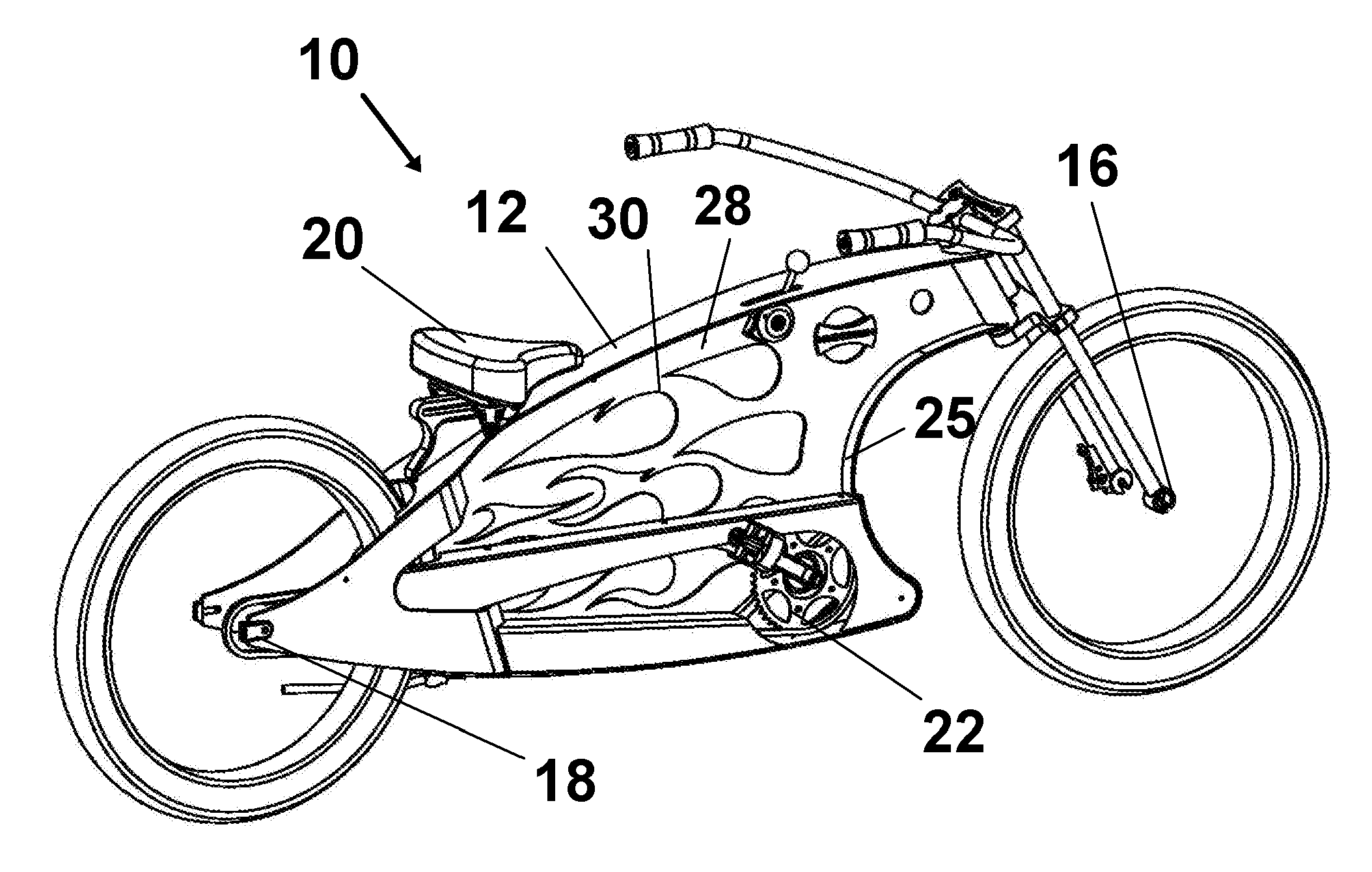
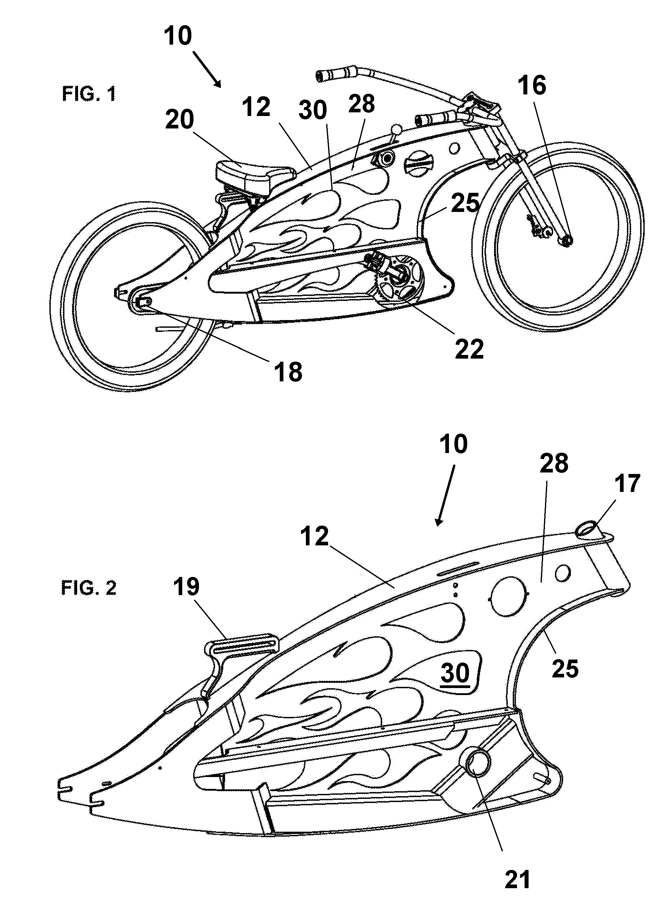
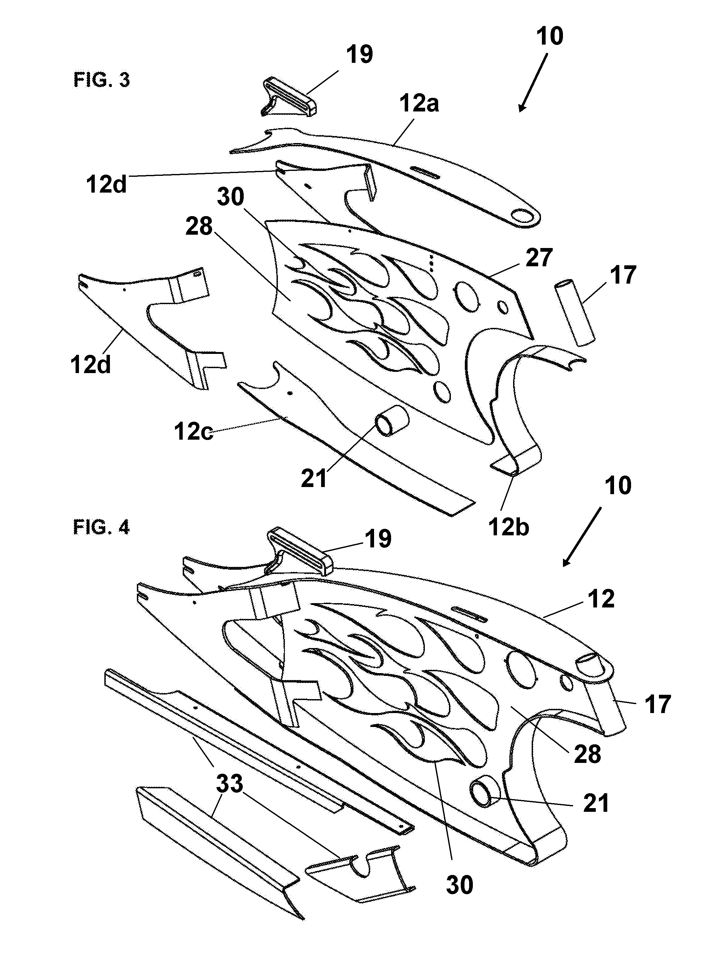
[0040]Referring now to the FIGS. 1-11, where similar components are depicted with the same numerals, the device 10 is shown in a fully assembled operative fashion in FIG. 1. The device 10 features a frame 12 formed of one or a combination of tubular or preferably sheet metal, or planar or tubular composite sections in a substantially conventional bike frame configuration. As shown in the drawings, and particularly preferred in all modes of the device 10 the frame 12 is formed of planar sheet metal, or planar formed composite. The sheet metal forming the frame 12 is substantially horizontally disposed when the frame 12 is being ridden by a rider in the as-used position where it would be upright as in FIG. 6.

[0041]The employment of planar sheet metal for the frame components 12a-12d which are operatively engaged with the vertically disposed planar member 28 and support struts form the frame 12 of sheet metal, yielding a very stable, yet easily mass-produced frame structure. The use of...


PUM


Abstract

A bicycle frame for employment in a bicycle for riding by a user in a substantially vertical as-used position. The frame has a shape which defines an aperture within the interior surface of a surrounding frame. The frame is preferably formed of planar material which has ends which do not block the view into the aperture when the bicycle is ridden. Whereby space for indicia on an inserted vertically disposed planar member is maximized. The planar member has a perimeter defining a shape that is complimentary to the shape of the aperture and when engaged therein provides support to the frame to prevent deformation thereof when in the as-used position under a load. The indicia positioned on the planar member may be advertising which can easily be changed using removable planar members with different indicia.

Description

[0001]This application claims priority to U.S. Provisional Application Ser. No. 61 / 366,054 filed on Jul. 20, 2010, and incorporated herein by reference in its entirety.BACKGROUND OF THE INVENTION[0002]1. Field of the Invention[0003]The invention herein disclosed relates generally to the art of bicycles. More particularly, it relates to a bicycle having a frame adapted for inclusion of a panel bearing indicia for advertising or decoration or both.[0004]2. Prior Art[0005]Bicycles have been a favored mode of transportation throughout the world for decades. Riders of bicycles the world over employ them for transportation to work and shopping. In addition to such basic transportation, bicycles are frequently employed for recreation and used in conjunction with the rider's course of employment.[0006]In the case of recreation, bicycles are ridden in races, over mountain trails, in packs of riders associated with each other or a common group, and simply for leisure riding such as when on va...

Claims


Application Information

Patent Timeline
IPC IPC(8): B60R13/00
CPCB62K19/08
Inventor MEREDITH, JEFFREY OWEN
Owner MEREDITH JEFFREY OWEN
Learn More