
Engine control apparatus for a vehicle and vehicle incorporating same

a technology of engine control apparatus and vehicle, which is applied in the direction of electric control, speed sensing governor, speed sensing device, etc., can solve the problems of reducing the engine speed, affecting the operation of the engine, and the variation of the engine speed momentarily reduced, so as to prevent the instantaneous drop of the engine speed, reduce the amount of intake air, and control the engine adequately

Active Publication Date: 2013-03-21
HONDA MOTOR CO LTD
View PDF7 Cites 1 Cited by
  • Summary
  • Abstract
  • Description
  • Claims
  • Application Information

AI Technical Summary

Benefits of technology

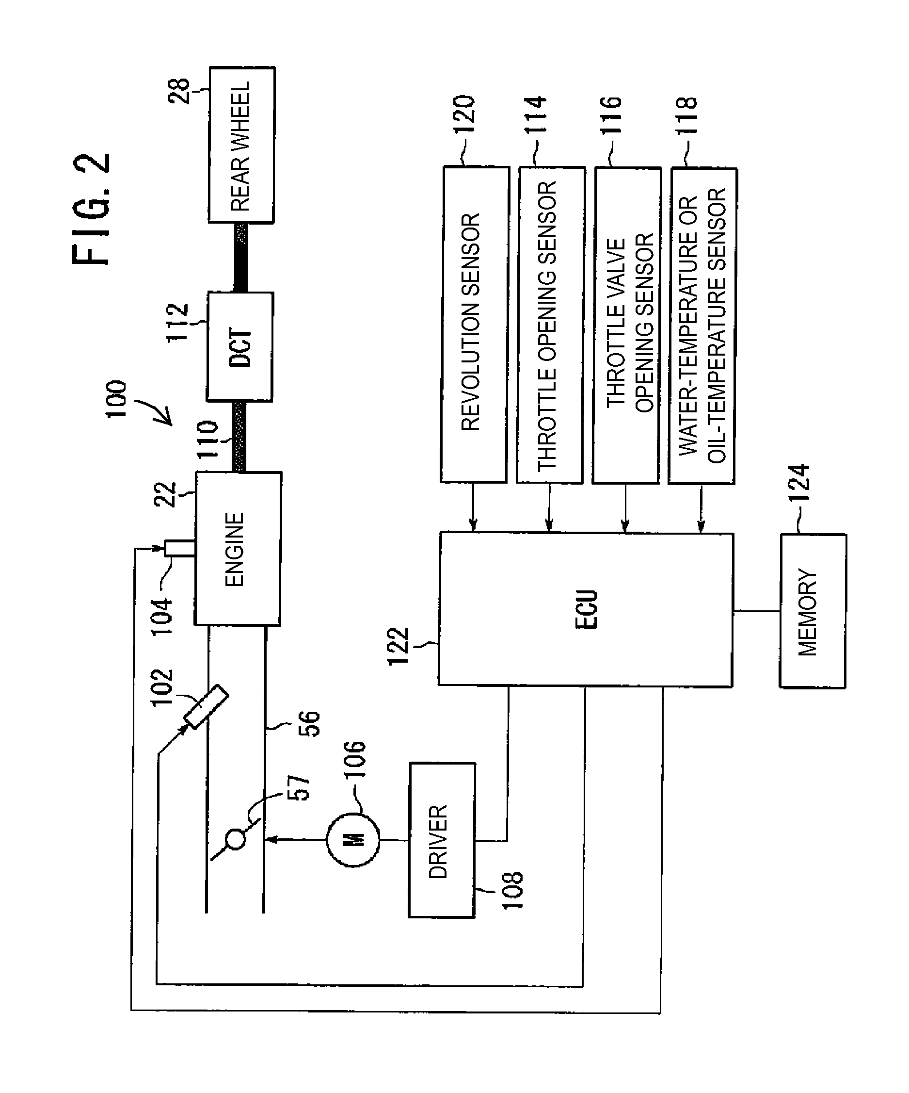
The present invention provides an engine control apparatus that can adjust the amount of intake air supplied to the engine and speed up the engine quickly during warm-up. The control unit uses a feedback control based on the amount of intake air and the engine speed to achieve the target idle speed. The control unit also takes into account the water and oil temperatures of the engine to adjust the amount of intake air. The control unit can determine whether the conditions for the feedback control are satisfied and execute the feedback control accordingly. The control unit can also confine the opening of the intake air flow control valve to achieve the desired amount of intake air.

Problems solved by technology

However, in the engine control system disclosed in Japanese Patent Document JP-A-2010-7585, since the amount of intake air is configured to be switched when the predetermined time has elapsed, increase in the engine speed is delayed when the water temperature or the oil temperature is low and friction is high, so that the predetermined time has elapsed and the amount of intake air is switched to a smaller value before the engine speed reaches a target idle speed, which may reduce the engine speed at the time of the switching and cause a variation that the engine speed is momentarily reduced.
Consequently, since the feedback control is performed with a smaller amount of intake air at the time point when the throttle is returned, the problem that the engine speed reduced temporarily is not resolved.

Method used


Image

  • Engine control apparatus for a vehicle and vehicle incorporating same
  • Engine control apparatus for a vehicle and vehicle incorporating same
  • Engine control apparatus for a vehicle and vehicle incorporating same

Examples


Embodiment Construction

[0039]An embodiment of the present invention will now be described, with reference to the drawings. Throughout this description, relative terms like “upper”, “lower”, “above”, “below”, “front”, “back”, and the like are used in reference to a vantage point of an operator of the vehicle, seated on the driver's seat and facing forward. It should be understood that these terms are used for purposes of illustration, and are not intended to limit the invention.

[0040]Referring now to the attached drawings, an engine control apparatus according to the invention will be described in detail below with reference to an illustrative embodiment.

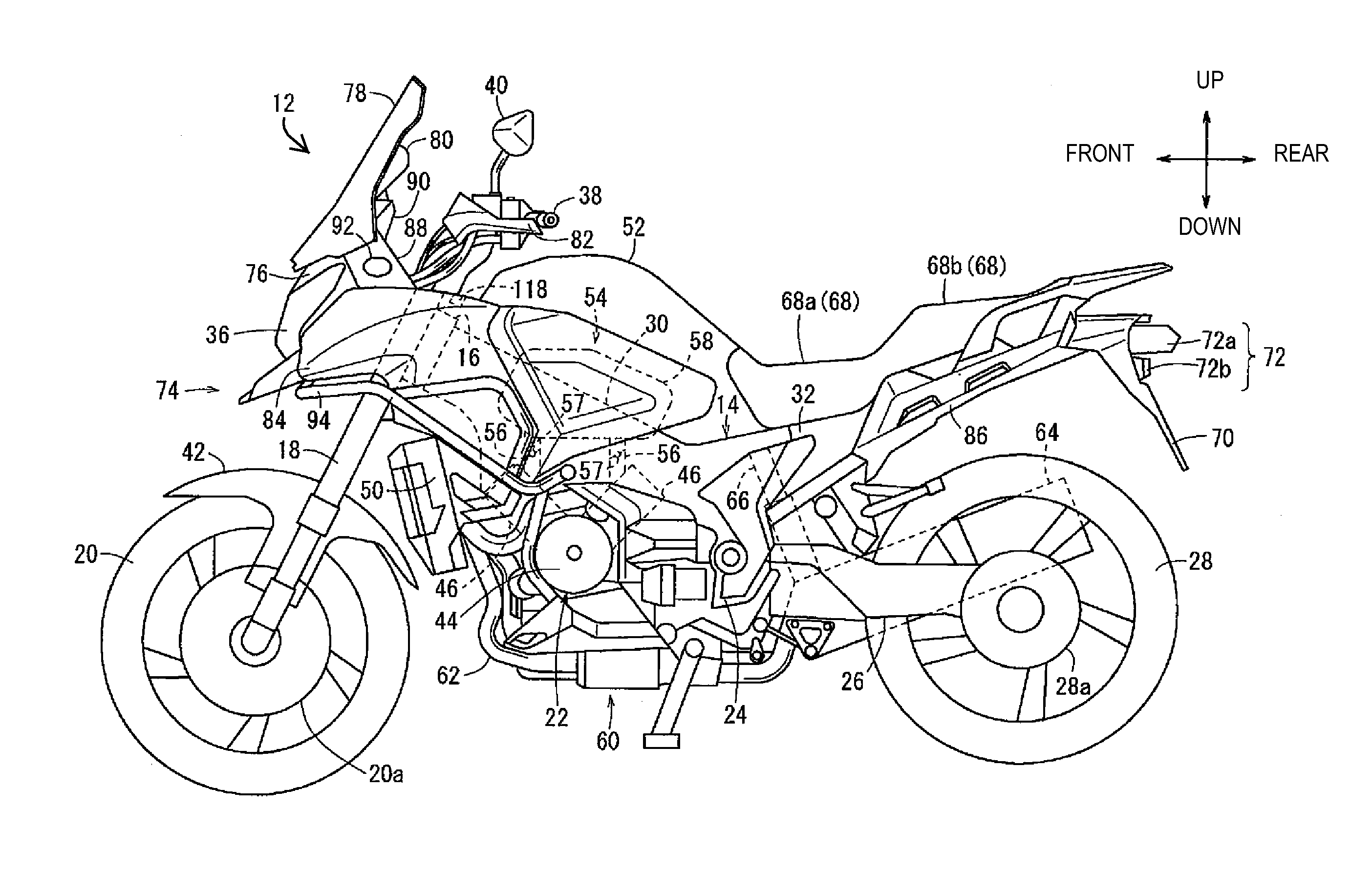
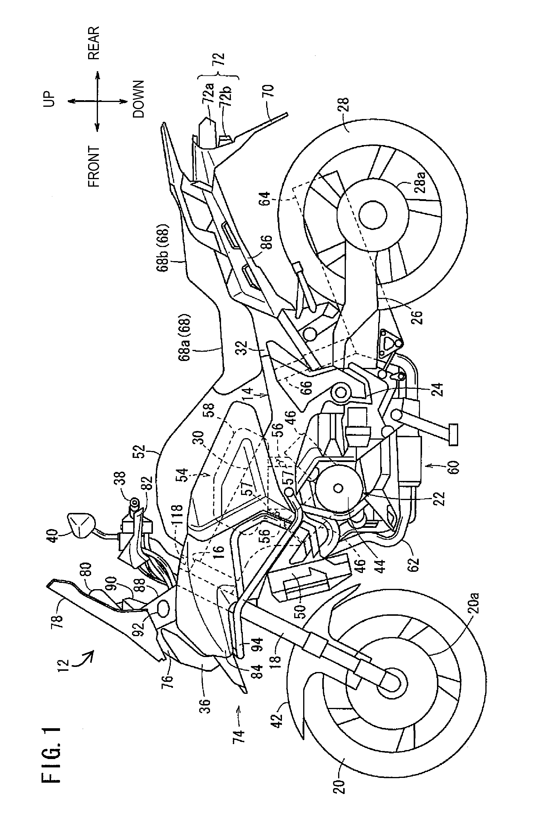
[0041]FIG. 1 is a schematic left side view of a saddle-type motorcycle (hereinafter, referred to as “motorcycle”) 12 having an engine control apparatus according to the illustrative embodiment of the present invention. For the facilitation of easy understanding of the invention, the fore-and-aft direction and the up and down directions are described with r...


PUM


Abstract

An engine control apparatus includes a control unit configured to perform a feedback control based on a second amount of intake air until a engine speed reaches a target idle speed. The engine control apparatus then regulates the amount of intake air to an amount smaller than a predetermined second amount of intake air for a predetermined period when the engine speed exceeds the target idle speed, and then performs a feedback control based on a first amount of intake air. Such engine control apparatus minimizes variation in engine speed by reducing a convergence time of the engine speed to a target idle speed in switching control of the amount of intake air in a case where engine friction at a low temperature is high.

Description

CROSS-REFERENCE TO RELATED APPLICATIONS[0001]The present invention claims priority under 35 USC 119 based on Japanese patent application No. 2011-201594, filed on Sep. 15, 2011. The entire subject matter of this priority document, including specification claims and drawings thereof, is incorporated by reference herein.BACKGROUND OF THE INVENTION[0002]1. Field of the Invention[0003]The present invention relates to an engine control apparatus for a vehicle and to a vehicle incorporating the same. More particularly, the present invention relates to an engine control apparatus configured to adjust the amount of intake air supplied to an engine, and to a vehicle incorporating the same.[0004]2. Description of the Background Art[0005]The Japanese Patent Document JP-A-2010-7585 discloses an engine control system which increases an intake air flow rate above a flow rate prescribed for a normal idling state, to increase a engine speed to approach a target idle speed, in order to activate an e...

Claims


Application Information

Patent Timeline
Patent Type & Authority Applications(United States)
IPC IPC(8): F02D41/26
CPCY02T10/26F02D41/0255F02D41/086F02D2200/101F02D2200/021F02D2200/0404F02D31/003Y02T10/12
Inventor NAKAMURA, MASANORIMACHIDA, KENICHI
Owner HONDA MOTOR CO LTD
Learn More