Exhaust gas purification device

a technology of exhaust gas and purification device, which is applied in the direction of exhaust treatment electric control, electrical control, machines/engines, etc., can solve the problems of deterioration of fuel consumption and/or bad condition of internal combustion engines, no sensors that can detect air/fuel ratios in the lean range with higher precision, and no emission sensor has been developed. , to achieve the effect of reducing the amount of intake air taken into the internal combustion engine, reducing the amount of intake air, and reducing the amount of intak

Inactive Publication Date: 2006-09-12
HONDA MOTOR CO LTD
View PDF11 Cites 65 Cited by
  • Summary
  • Abstract
  • Description
  • Claims
  • Application Information

AI Technical Summary

Benefits of technology

[0009]According to this aspect of the invention, when the estimated amount of the particulates trapped by the particulate filter exceeds a threshold value, the particulate filter regeneration process is performed in which the exhaust gas temperature is raised in order to burn and remove the particulates. During this regeneration process, the combustion in the internal-combustion engine is kept in a desirable condition while the intake air amount is being reduced, so that the deterioration of the emission during the filter cleaning process can be avoided while the exhaust gas temperature is raised.
[0010]In the above-described structure, “means for decreasing the intake air amount” specifically includes, for example, a throttle valve disposed in an air intake system of the internal-combustion engine or a supercharger disposed in an exhaust system of the internal-combustion engine. As for the former case, the intake air amount that is taken into the internal-combustion engine is decreased by closing the throttle valve. As for the latter case, the thermal energy supplied to the air intake system of the internal-combustion engine is decreased by decreasing the supercharging pressure by the supercharger, so that the intake air amount is reduced.
[0011]Besides, the above-described “means for maintaining combustion” specifically includes, for example, a swirl control valve or an EGR (Emission Gas Recirculation) valve. As for the former case, the swirl strength inside the combustion chamber of the internal-combustion engine is increased by closing the swirl control valve, so that the combustion in the internal-combustion engine can be improved. As for the latter case, the deterioration of the emission during the exhaust stroke of the internal-combustion engine is prevented by closing the EGR valve. As for the EGR valve, in some situations, the emission may be improved by opening the EGR valve. Therefore, the opening or closing of the EGR valve is determined according to the characteristic of the internal-combustion engine.

Problems solved by technology

The increase in the exhaust gas pressure may cause a backpressure to the internal-combustion engine, which may further result in deterioration of fuel consumption and / or bad condition of the internal-combustion engine.
However, when the fuel is supplied to the exhaust pipe, reduction of the intake air amount in order to raise the exhaust gas temperature produces a problem that the emission gets worse due to deterioration of the combustion condition of the internal-combustion engine.
No sensors that can detect the air / fuel ratio in the lean range with higher precision have been developed.
Thus, there are no systems for performing a feedback control of the air / fuel ratio of the exhaust gas.
For this reason, there are such problems as the emission gets worse due to instability of the air / fuel ratio of the exhaust gas, and as the regeneration process for the particulate filter cannot be stabled due to instability of the exhaust gas temperature when the particulate filter is cleaned through post-injection.

Method used


Image

  • Exhaust gas purification device
  • Exhaust gas purification device
  • Exhaust gas purification device

Examples


embodiment 1 (

CORRECTION OF THE FUEL INJECTION AMOUNT)

[0071]FIG. 6 shows the first embodiment of the air / fuel ratio feedback loop. This embodiment controls the air / fuel ratio of the exhaust gas to be constant during the particulate filter regeneration process by detecting the air / fuel ratio of the exhaust gas and corrects the fuel injection amount based on the detected air / fuel ratio. A flowchart of this process is shown in FIG. 7.

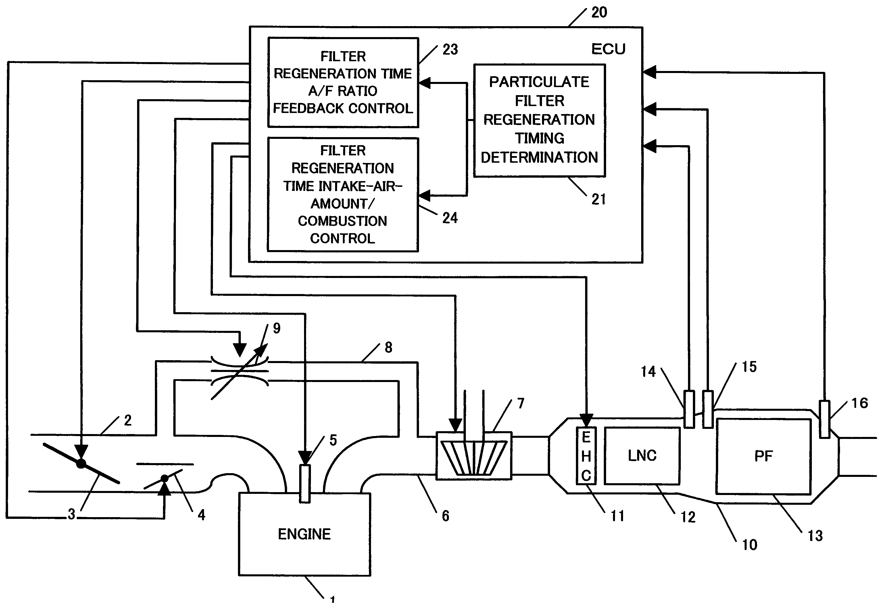
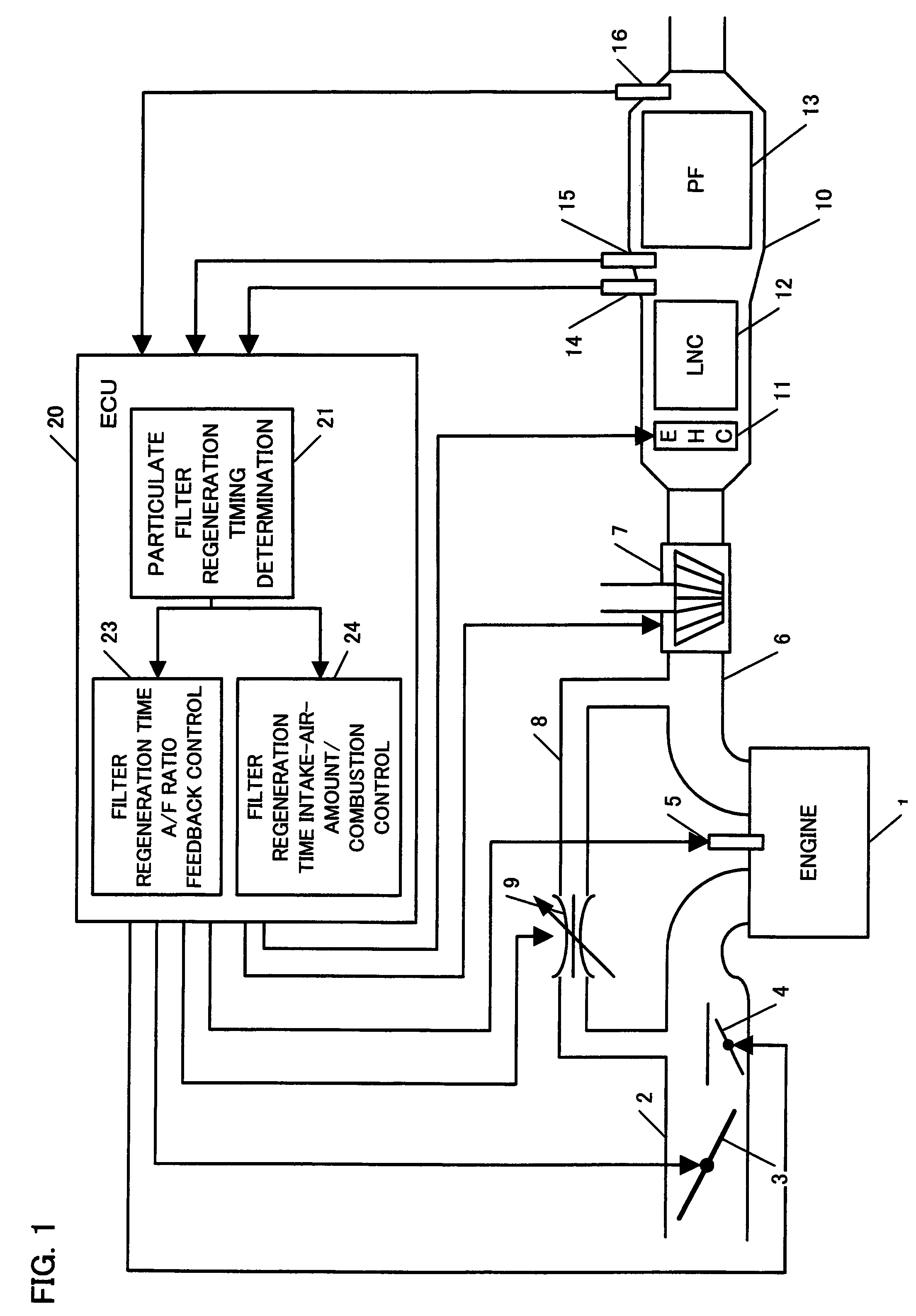
[0072]At first, a variation amount of the accelerator pedal is detected to calculate a request torque (S100). The throttle valve is opened in accordance with the request torque, so that the air is taken in (S102). Next, a map that is predetermined with respect to intake air amounts and engine rotational speeds is searched to calculate the fuel injection amount (S104), for combustion in the engine 1. Next, an error between the exhaust air / fuel ratio detected by the LAF sensor 14 and the desired air / fuel ratio for the exhaust gas is calculated (S106), a post-injection amo...

embodiment 2 (

CORRECTION OF THE INTAKE AIR AMOUNT)

[0073]Even though the embodiment 1 allows for achievement of the objective that the exhaust air / fuel ratio be kept constant, it is preferable to extend a conventional approach to perform an air / fuel feedback control rather than newly providing the means for calculating the fuel injection amount because the ordinary diesel engine control adopts an open loop control by which the fuel is supplied in accordance with the accelerator opening regardless of the intake air amount. Therefore, as shown in FIG. 8, the second embodiment of the air / fuel ratio feedback loop controls the air / fuel ratio of the exhaust gas to be constant during the particulate filter regeneration process by detecting the air / fuel ratio of the exhaust gas and correcting the intake air amount to be taken into the engine 1 based on the detected air / fuel ratio. A flowchart of this process is shown in FIG. 9.

[0074]At first, a variation amount of the accelerator pedal is detected to calc...


PUM


Abstract

The invention provides an exhaust gas purification device that can prevent deterioration of the emission during a regeneration process for a particular filter for trapping particulates contained in the exhaust gas.
Particulate filter regeneration timing determining unit estimates the amount of particulates trapped by the particulate filter to determine the filter regeneration timing based on the estimated particular amount. In response to the regeneration timing determination, heating unit heats the particulate filter to raise an exhaust gas temperature, so that a particulate filter regeneration process starts. At this time, intake air amount reducing unit reduces the intake air amount to raise the exhaust gas temperature while combustion maintaining unit controls the combustion in the internal-combustion engine so as to be maintained in a desired condition.

Description

BACKGROUND OF THE INVENTION[0001]The present invention relates to an exhaust gas purification device for an internal-combustion engine, and more particularly it relates to a control scheme for burning and removing suspended particle matters (SPM, hereinafter referred to as a “particulate”) which are generated from an internal-combustion engine and trapped by a particulate filter that is operable to trap and remove the particulates.[0002]Particulates which are exhausted from an internal-combustion engine includes such particle matters as soot particles, various hydrocarbon particles and other insoluble organic matters (SOOT) on which unburned fuel, unburned oil constituents and other soluble organic matters (SOF) and / or sulfur oxide matters are deposited, the sulfur oxide matters being produced. There has been conventionally developed a diesel particulate filter (DPF) for trapping those particulates contained in the exhaust gas. Through use of such particulate filter, it is possible ...

Claims


Application Information

Patent Timeline
Patent Type & Authority Patents(United States)
IPC IPC(8): F01N3/00F02D9/02F01N3/02F01N3/025F02D41/02F02D41/04F02D41/14F02D41/40F02D45/00F02M45/00F02M45/06F02M45/12F02M47/02F02M59/36F02M59/46
CPCF01N3/0253F01N3/027F01N9/002F01N13/009F02D41/029F01N2560/025F01N2560/06F02B37/00F02D41/405F02D2041/1418Y02T10/47F01N2560/08Y02T10/40
Inventor SHIMASAKI, YUICHIYAMAGUCHI, SATOSHI
Owner HONDA MOTOR CO LTD
Why Eureka
Try Eureka