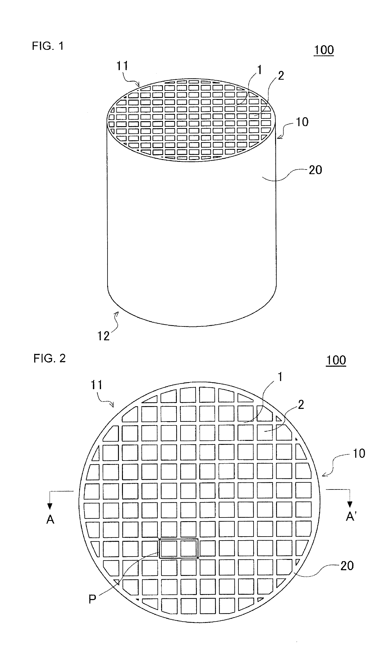
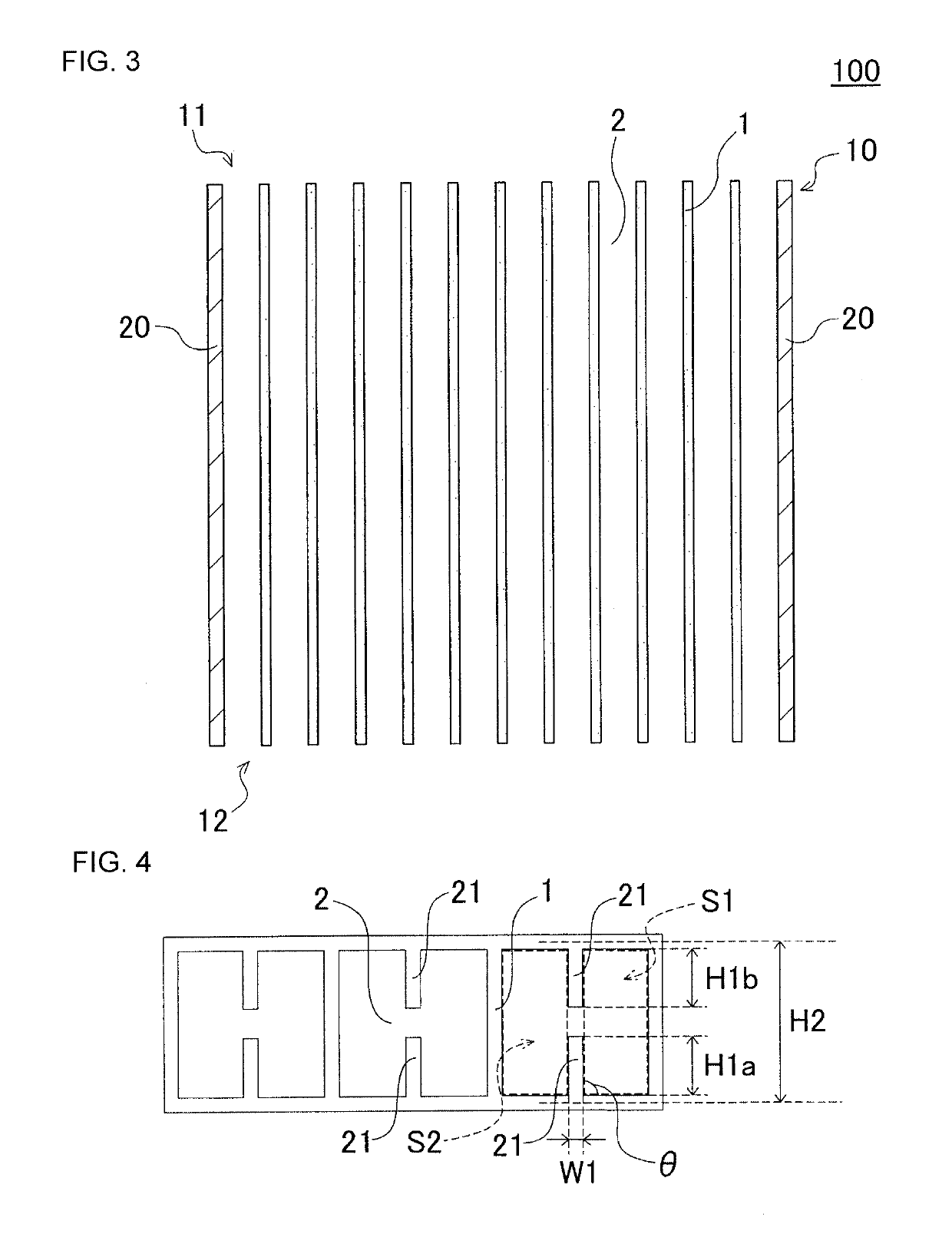
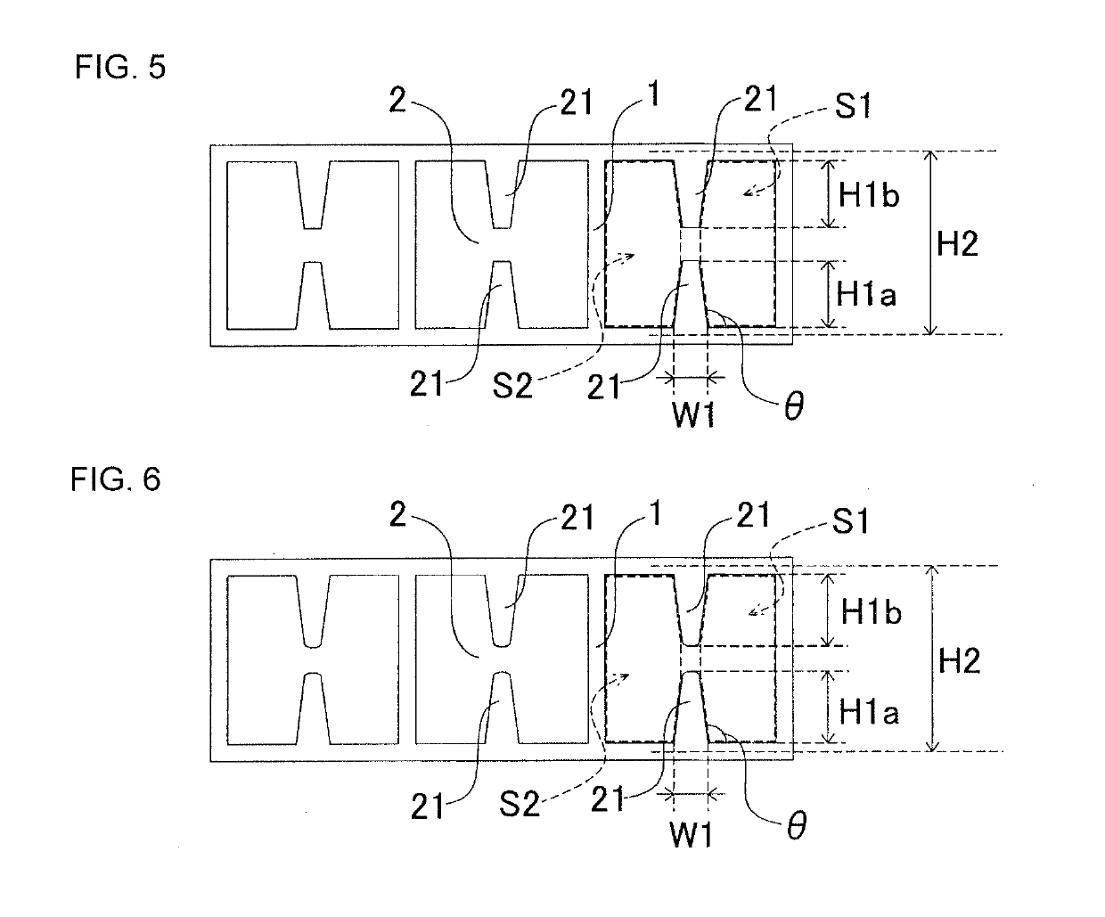
Honeycomb structure

a honeycomb and structure technology, applied in the field of honeycomb structure, can solve the problems emissions deterioration, and achieve the effect of suppressing the occurrence of gas flow stagnation, increasing the geometrical surface area of partition walls, and increasing the quantity of projections

Active Publication Date: 2019-10-03
NGK INSULATORS LTD
View PDF0 Cites 0 Cited by
  • Summary
  • Abstract
  • Description
  • Claims
  • Application Information

AI Technical Summary

Benefits of technology

[0017]The honeycomb structure in accordance with the present invention has the projections provided such that the projections project into the cells, thus making it possible to increase the geometrical surface areas of the partition walls by the projections. Further, since among the partition walls surrounding one cell, the projections are provided only on the partition walls that constitute the two sides opposing each other of the cell sandwiched therebetween, an excessive increase of the quantity of the projections can be suppressed, and the occurrence of the stagnation of a gas flow can be effectively suppressed. The honeycomb structure in accordance with the present invention provides effect for suppressing the deterioration of emissions and for improving purification performance.

Problems solved by technology

However, placing the fins as described in Patent Document 1 involves many portions closed by the fins relative to the space used as the through channels in the cells, which easily leads to stagnation of a gas flow.
This has caused a problem in that a gas flow is locally concentrated in one cell, leading to deterioration of emissions, especially under high load in a driving mode of an automobile.

Method used


Image

  • Honeycomb structure
  • Honeycomb structure
  • Honeycomb structure

Examples


example 1

[0064]In Example 1, a forming raw material for fabricating the honeycomb structure was first prepared. More specifically, a binder, a surfactant, a pore former, and water were added to a ceramic raw material to make the forming raw material. As the ceramic raw material, kaolin, talc and alumina, which are cordierite forming raw materials, were used.

[0065]Next, the obtained forming raw material was kneaded by a kneader, and then soil kneading was performed by a vacuum pugmill to make a kneaded material. Next, the obtained kneaded material was extrusion-molded by using a die to make a honeycomb formed body. The die used was a die in which a region that is complementary with a projection (a region which will become a projection by the entry of the kneaded material) is formed. After the honeycomb formed body was fired, the thickness of the partition wall thereof was 0.09 mm, and the cell density was 62 cells / cm2. The shape of the cells of the honeycomb formed body was tetragon. The hone...


PUM

PropertyMeasurementUnit
angleaaaaaaaaaa
thicknessaaaaaaaaaa
width W1aaaaaaaaaa

Abstract

A honeycomb structure includes a pillar-shaped honeycomb structure body which has porous partition walls disposed to surround a plurality of cells Among the partition walls surrounding one of the cells, each of the partition walls constituting two opposite sides of the cell sandwiched therebetween is provided with a projection which project to extend into the cell and which is continuously provided in a direction in which the cell extends, and the area S1 of one region of the cell divided by a virtual line that virtually connects distal ends of the two projections in a section of the honeycomb structure body, and the area S2 of the other region (S1≤S2) of the cell satisfy 70%≤S1/S2×100%.

Description

[0001]The present application is an application based on JP 2018-066770 filed on Mar. 30 2018 with Japan Patent Office, the entire contents of which are incorporated herein by reference.BACKGROUND OF THE INVENTIONField of the Invention[0002]The present invention relates to a honeycomb structure. More specifically, the present invention relates to a honeycomb structure which can be ideally used especially as a catalyst carrier adapted to load a catalyst for purifying exhaust gas.Description of the Related Art[0003]In recent years, the awareness of environmental issues has been increasing throughout society. Hence, in the field of technology for generating motive power by burning fuels, various technologies for removing harmful components, such as nitrogen oxides, from exhaust gas generated when a fuel is burnt have been developed. For example, various technologies for removing harmful components, such as nitrogen oxides, from the exhaust gas emitted from automobile engines have been ...

Claims


Application Information

Patent Timeline
Patent Type & Authority Applications(United States)
IPC IPC(8): B01J35/04B01D53/94B01J37/02B01J37/08F01N3/28
CPCB01J35/04F01N3/2821B01J37/0215B01J37/08B01D53/94F01N3/2803F01N2330/06F01N3/28F01N3/2828F01N2330/32B01D2258/01B01D2253/3425B01D53/9463F01N2330/38
Inventor KINOSHITA, TAKASHI
Owner NGK INSULATORS LTD
Why Eureka
Try Eureka