Engine control device

a technology of engine control and catalyst device, which is applied in the direction of electric control, machines/engines, mechanical equipment, etc., can solve the problems of device cannot store surplus oxygen, and reduce the exhaust emission control capability of the catalyst device, so as to curb a deterioration in engine emissions, the effect of less likely reduction of the exhaust emission control performance of the catalyst devi

Active Publication Date: 2022-10-04
TOYOTA JIDOSHA KK
View PDF4 Cites 0 Cited by
  • Summary
  • Abstract
  • Description
  • Claims
  • Application Information

AI Technical Summary

Benefits of technology

[0010]On the other hand, when the rich combustion is performed in the catalyst device, hydrocarbons in exhaust gas are adsorbed on the surface of precious metal serving as the three-way catalyst. Some of the adsorbed hydrocarbons are polymerized into higher hydrocarbons. Due to coating of the surface of the precious metal with higher hydrocarbons, a catalytic reaction of the precious metal is inhibited. When fuel cutoff is performed in the engine and a large amount of oxygen flows into the catalyst device, the higher hydrocarbons with which the surface of the precious metal is coated are oxidized and removed from the surface of the precious metal. When the combustion operation of the engine continues to be performed for a long time without being stopped by fuel cutoff, an exhaust emission control capability of the catalyst device decreases.
[0011]In this way, both the shortening of the occurrence cycle of the lean failure and the rich failure due to an increase in opening level of the waste gate valve and the coating of the surface of the precious metal with higher hydrocarbons serve as causes of deterioration in the emissions of the engine. On the other hand, with the engine control device, the upper limit of the control range of the opening level of the waste gate valve is set to be less when the combustion operation of the engine continues to be performed for a long time without being stopped than otherwise through the limiting process. That is, in a state in which the exhaust emission control performance of the catalyst device has decreased due to coating with higher hydrocarbons, the opening level of the waste gate valve is not set to be high. Accordingly, it is possible to prevent the two factors causing a deterioration in emissions from occurring simultaneously. As a result, with the engine control device, it is possible to curb a deterioration in emissions of the engine.
[0012]When a load of the engine changes greatly without performing fuel cutoff, exhaust gas including oxygen may flow into the catalyst device in this course of change and higher hydrocarbons with which the surface of the precious metal is coated may be removed. Accordingly, when the combustion operation of the engine continues to be performed for a long time without being stopped by fuel cutoff and the load of the engine changes greatly, the exhaust emission control performance of the catalyst device is less likely to decrease due to coating with higher hydrocarbons. In this case, the limiting process in the engine control device can be performed based on the premise that fluctuation in engine load is small.

Problems solved by technology

However, when a combustion operation of the engine continues to be performed for a long time without being stopped by fuel cutoff, an exhaust emission control capability of the catalyst device decreases because the catalytic reaction of the precious metal is inhibited due to the coating with higher hydrocarbons.
The inhibition of the catalytic reaction of a precious metal due to the coating with higher hydrocarbons and the change of the method in which exhaust gas comes into contact with the catalyst device depending on the opening level of the waste gate valve may together cause deterioration in the emissions of the engine.
When lean combustion continues to be performed, the catalyst device cannot store surplus oxygen any more at last and exhaust gas including surplus oxygen flows out, that is, a lean failure occurs.
When rich combustion continues to be performed, the catalyst device discharges all oxygen stored therein at last and exhaust gas including an unused fuel component flows out, that is, a rich failure occurs.
Accordingly, when the opening level of the waste gate valve is high, a flow of exhaust gas in the catalyst device is biased and an occurrence cycle of the lean failure and the rich failure is shortened.
When the lean failure occurs, an amount of NOx discharged from the catalyst device increases temporarily.
When the rich failure occurs, an amount of THC discharged from the catalyst device increases temporarily.
In this way, both the shortening of the occurrence cycle of the lean failure and the rich failure due to an increase in opening level of the waste gate valve and the coating of the surface of the precious metal with higher hydrocarbons serve as causes of deterioration in the emissions of the engine.
On the other hand, with the engine control device, the upper limit of the control range of the opening level of the waste gate valve is set to be less when the combustion operation of the engine continues to be performed for a long time without being stopped than otherwise through the limiting process.
In a state in which the catalyst device has not deteriorated, even when fuel cutoff is not performed for a long time, the exhaust emission control performance may not decrease due to coating with higher hydrocarbons.

Method used


Image

  • Engine control device
  • Engine control device
  • Engine control device

Examples


first embodiment

[0030]Hereinafter, an engine control device according to a first embodiment will be described in detail with reference to FIGS. 1 to 12. The engine control device according to this embodiment is applied to an engine with a turbocharger which is mounted in a vehicle.

Configuration of Engine Control Device

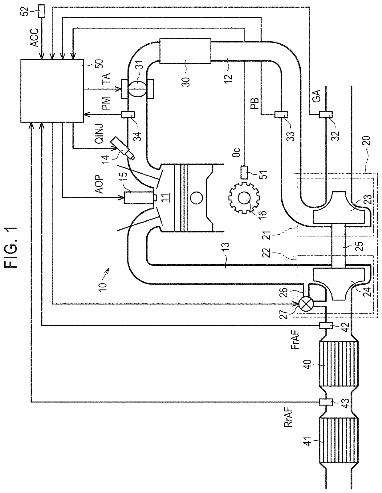
[0031]A configuration of an engine 10 to which an engine control device 50 according to this embodiment is applied will be first described below with reference to FIG. 1. The engine 10 includes a combustion chamber 11 in which combustion of an air-fuel mixture is performed. The engine 10 includes an intake air passage 12 which is an introduction passage of intake air into the combustion chamber 11 and an exhaust passage 13 which is a discharge passage for exhaust gas from the combustion chamber 11. The engine 10 includes a plurality of cylinders and includes the combustion chamber 11 for each cylinder. Only one of a plurality of combustion chambers 11 is illustrated in FIG. 1. In the ...

second embodiment

[0077]An engine control device 50 according to a second embodiment will be described below in detail with additional reference to FIG. 11. The configuration of the engine control device 50 according to this embodiment is the same as the configuration in the first embodiment except details of the limiting process P6. In this embodiment and embodiments which will be described later, the same elements as in the aforementioned embodiment will be referred to by the same reference signs and detailed description thereof will not be repeated.

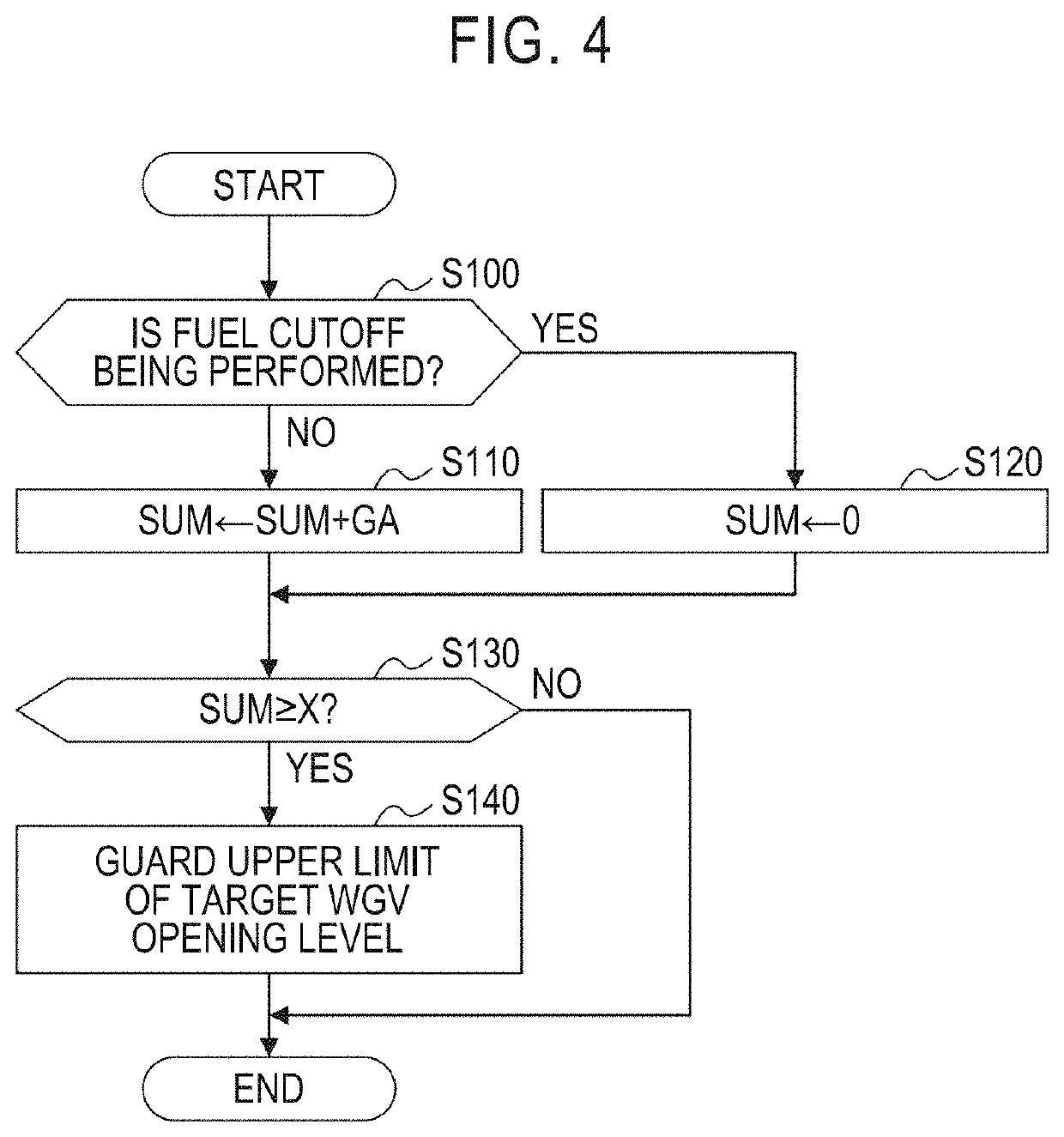
[0078]FIG. 11 illustrates a process routine associated with the limiting process P6 in the engine control device 50 according to this embodiment. The processes of Steps S100 to S140 in FIG. 11 are the same as the processes of Steps S100 to S140 in FIG. 4.

[0079]In the engine control device 50 according to this embodiment, before the limiting process P6, it is determined in Step S10 whether a state in which fluctuation of the engine load factor KL is smal...

third embodiment

[0081]An engine control device 50 according to a third embodiment will be described below in detail with additional reference to FIG. 12. The engine control device 50 according to this embodiment is mounted in a vehicle in which cruise control for automatically operating an accelerator to maintain a vehicle speed at a preset speed can be performed.

[0082]FIG. 12 illustrates a process routine associated with the limiting process P6 in the engine control device 50 according to this embodiment. The processes of Steps S100 to S140 in FIG. 12 are the same as the processes of Steps S100 to S140 in FIG. 4.

[0083]In the engine control device 50 according to this embodiment, before the limiting process P6, it is determined in Step S20 whether cruise control is being performed. When cruise control is not being performed (NO), the routine illustrated in FIG. 12 ends without performing the limiting process P6 in the current control cycle. On the other hand, when cruise control is being performed ...


PUM


Abstract

An engine control device performs air-fuel ratio control of an engine through a main air-fuel ratio feedback process based on an output of a front air-fuel ratio sensor, a sub air-fuel ratio feedback process of alternately switching a target air-fuel ratio between a lean-side target air-fuel ratio and a rich-side target air-fuel ratio based on an output from a rear air-fuel ratio sensor. The engine control device performs a limiting process of setting an upper limit of a control range of an opening level of a waste gate valve to be less when a combustion operation of the engine continues to be performed for a long time without being stopped by fuel cutoff than otherwise.

Description

CROSS-REFERENCE TO RELATED APPLICATION[0001]This application claims priority to Japanese Patent Application No. 2021-021777 filed on Feb. 15, 2021, incorporated herein by reference in its entirety.BACKGROUND1. Technical Field[0002]The disclosure relates to an engine control device that performs air-fuel ratio control in a supercharged engine.2. Description of Related Art[0003]An engine such as an onboard engine including a catalyst device for exhaust emission control that carries a three-way catalyst and has an oxygen storage capability is known. A control device for an engine equipped with such a catalyst device in which an air-fuel ratio of an air-fuel mixture which is combusted in a combustion chamber is controlled through the two of main and sub air-fuel ratio feedback processes is also known. In the main air-fuel ratio feedback process, feedback control of an amount of fuel injected from an injector is performed such that the air-fuel ratio of the air-fuel mixture reaches a tar...

Claims


Application Information

Patent Timeline
Patent Type & Authority Patents(United States)
IPC IPC(8): F02B37/18F02D41/02F02D41/32F02D41/14
CPCF02B37/183F02D41/0235F02D41/1454F02D41/32F02D2200/04F02D2200/501F02D41/0007F01N3/101F02B37/025F02B37/18F02D2200/0406F02D41/1475F02D41/1441F02D41/0295Y02T10/12
Inventor YOSHIOKA, SHINJINAKAGOSHI, SHINICHI
Owner TOYOTA JIDOSHA KK
Why Eureka
Try Eureka