Control circuit and method for reducing output ripple in constant on-time switching regulator

a control circuit and output ripple technology, applied in the direction of dc-dc conversion, power conversion systems, instruments, etc., can solve the problem of high output ripple of circuits, and achieve the effect of reducing output rippl

Inactive Publication Date: 2012-01-26
RICHTEK TECH
View PDF3 Cites 50 Cited by
  • Summary
  • Abstract
  • Description
  • Claims
  • Application Information

AI Technical Summary

Benefits of technology

[0008]An objective of the present invention is to provide a control circuit for reducing output ripple in a COT switching regulator.

Problems solved by technology

The prior art has a drawback that the pulse generated by the one-shot pulse generator 60 has a fixed on-time, that is, in each cycle a fixed amount of power is transferred from the input side to the output side.
Thus, when the circuit operates in a very light load condition, too much energy is accumulated in the output capacitor C so that the circuit generates high output ripple.

Method used


Image

  • Control circuit and method for reducing output ripple in constant on-time switching regulator
  • Control circuit and method for reducing output ripple in constant on-time switching regulator
  • Control circuit and method for reducing output ripple in constant on-time switching regulator

Examples


Embodiment Construction

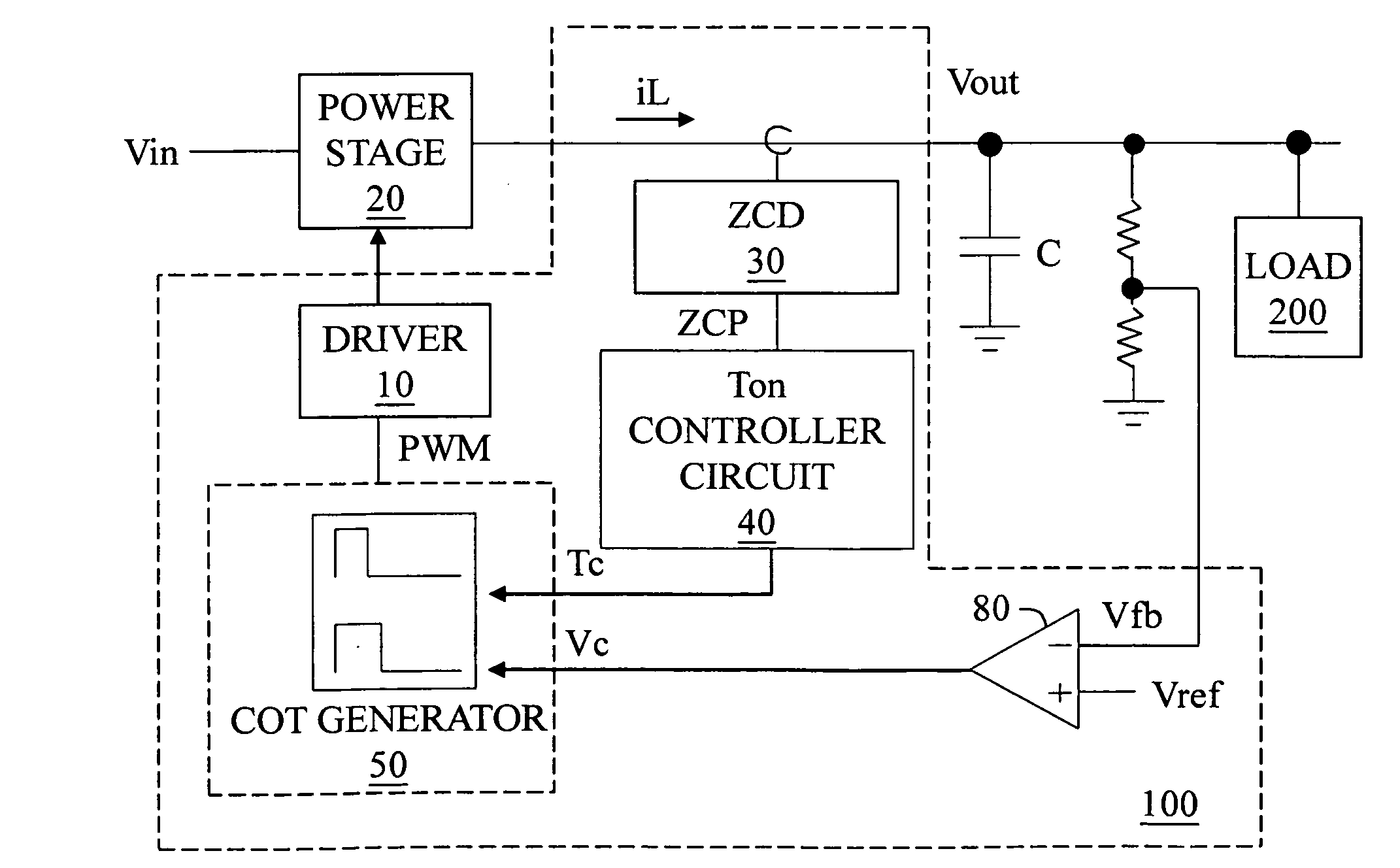
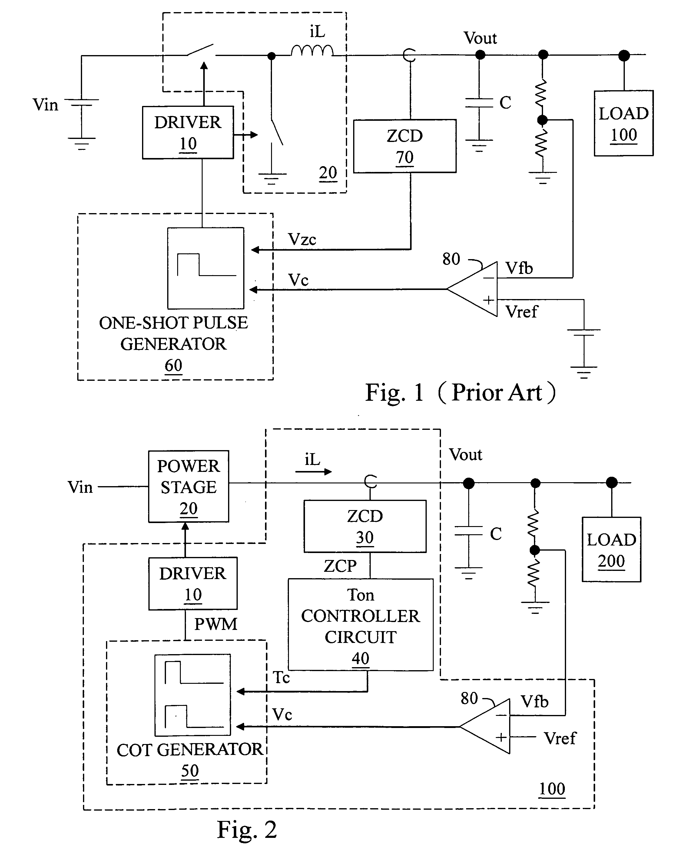
[0037]FIG. 2 shows a structure of the present invention, wherein a control circuit 100 for reducing output ripple in a COT switching regulator controls a power stage 20 to convert an input voltage Vin to an output voltage Vout and to provide an output current iL to a load 200. The power stage 20 may be, as shown for example, a synchronous buck converter, but also may be other types of synchronous or asynchronous buck, boost or inverting converters. The control circuit 100 includes: a zero current detector (ZCD) 30, an on-time (TON) adjustment circuit 40, and a constant on-time (COT) generation circuit 50. In certain applications, the control circuit 100 also includes a driver 10 and a comparator 80, while in other applications, the driver 10 is not integrated in the control circuit 100. The ZCD 30 generates a zero current period signal ZCP according to the inductor current iL from the power stage 20. The on-time (TON) adjustment circuit 40 generates a TON control signal Tc according...


PUM


Abstract

The present invention discloses a control circuit for reducing output ripple in a constant on-time switching regulator and a method thereof, for controlling a power stage. The control circuit determines whether a zero current period wherein an output current is zero is longer than a threshold period, and switches the on-time period to a shorter period if it is longer, whereby the power stage operates according to the shorter period while still in the discontinuous conduction mode (DCM).

Description

CROSS REFERENCE[0001]The present invention claims priority to TW 099124577, filed on Jul. 26, 2010.BACKGROUND OF THE INVENTION[0002]1. Field of Invention[0003]The present invention relates to a control circuit for reducing output ripple in a constant on-time switching regulator and a method thereof, wherein when the circuit is in light load condition, the on-time is shortened for reducing the output ripple, while the whole circuit still operates in a discontinuous conduction mode (DCM).[0004]2. Description of Related Art[0005]Switching regulators can be classified into two types according to how its power switch is controlled: pulse-width modulation type and frequency modulation type. In a frequency modulation type switching regulator, a circuit controlling the power switch generates a constant ON time so that the power switch is turned ON for the same time period every cycle. The whole circuitry, by modulating the frequency, adjusts the level of an output voltage to regulate the vo...

Claims


Application Information

Patent Timeline
Patent Type & Authority Applications(United States)
IPC IPC(8): G05F1/10
CPCH02M3/156H02M1/14
Inventor TSAI, YU-NUNG
Owner RICHTEK TECH
Why Eureka
Try Eureka