

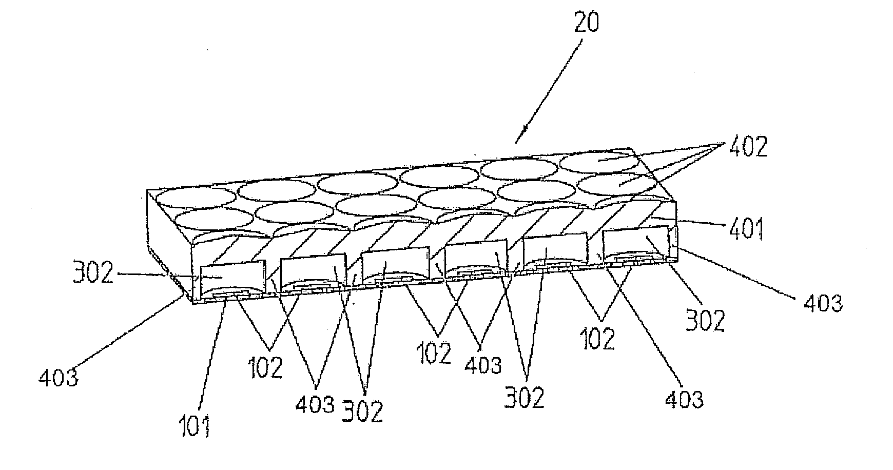
Planar antenna with cover
a planar antenna and cover technology, applied in the field of planar antennas, can solve the problems of low small bandwidth available, and high negative influence on the hf properties of individual planar radiator elements, and achieve the effects of high chemical resistance, easy work, and high chemical resistan
- Summary
- Abstract
- Description
- Claims
- Application Information
AI Technical Summary
Benefits of technology
Problems solved by technology
Method used
Image

Examples
Embodiment Construction
[0043]Reference will now be made in detail to several embodiments of the invention that are illustrated in the accompanying drawings. Wherever possible, same or similar reference numerals are used in the drawings and the description to refer to the same or like parts or steps. The drawings are in simplified form and are not to precise scale. For purposes of convenience and clarity only, directional terms, such as top, bottom, up, down, over, above, and below may be used with respect to the drawings. These and similar directional terms should not be construed to limit the scope of the invention in any manner. The words “connect,”“couple,” and similar terms with their inflectional morphemes do not necessarily denote direct and immediate connections, but also include connections through mediate elements or devices.
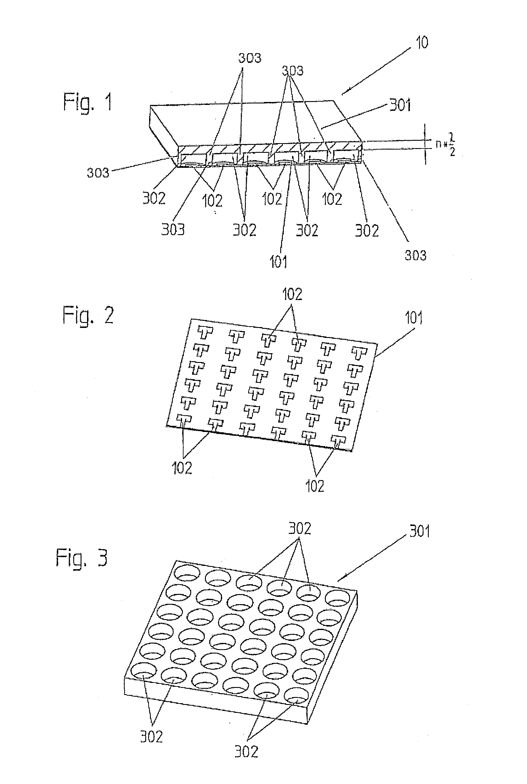
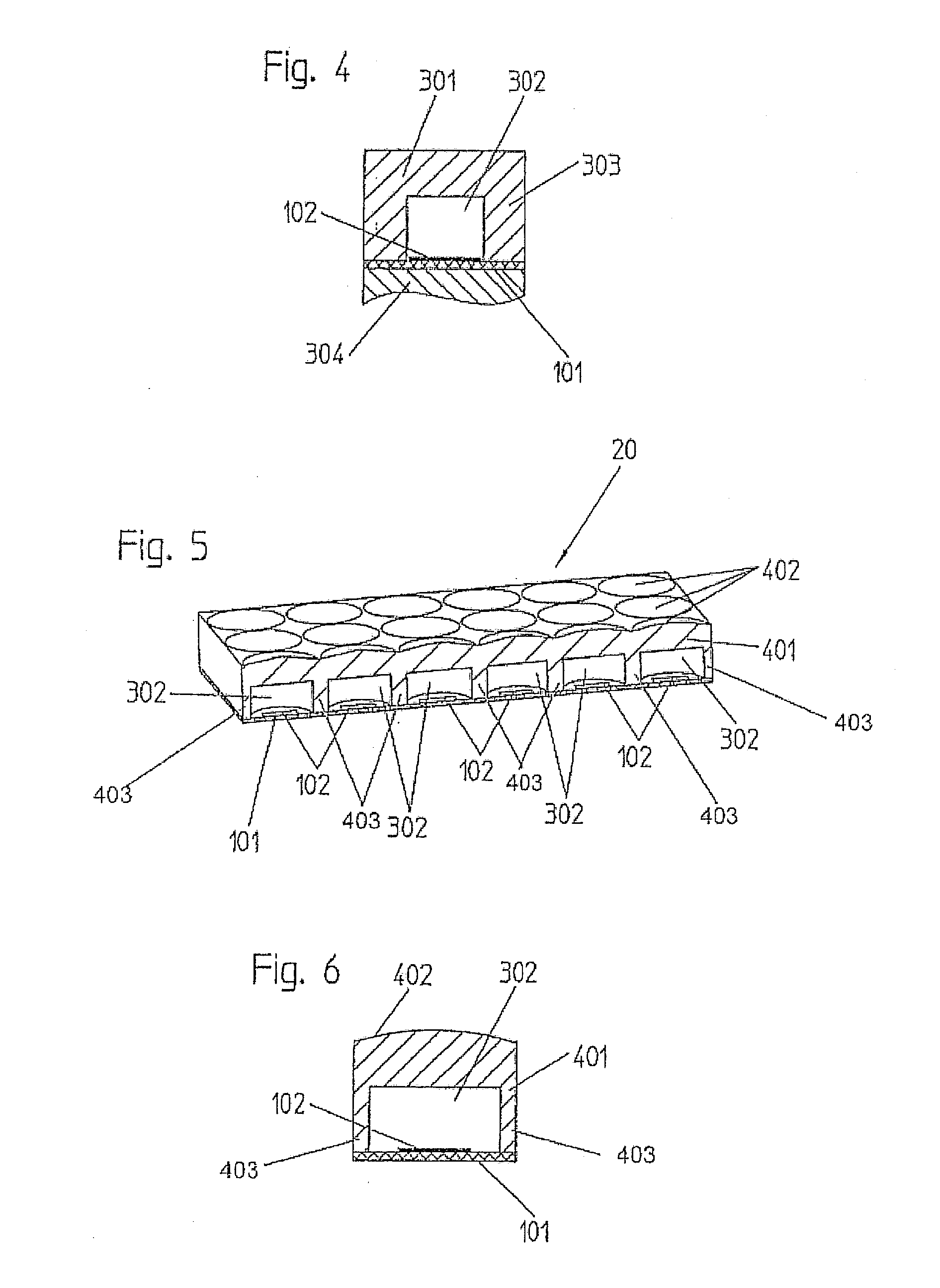
[0044]A first sample embodiment is shown by FIG. 1 to 4 in different representations. The planar antenna 10 of FIG. 1 comprises a substrate 101, which according to FIG. 2 has...
PUM
 Abstract
Description
Claims
Application Information