Information processing apparatus and control method thereof

a technology of information processing and control method, applied in the field of information processing, can solve the problems of inaccurate determination of the shape detection or position detection includes errors, and the detecting apparatus is unable to accurately determine whether or not the operator's motion is accurate, etc., to achieve accurate specification of the target object operated, accurate reflection, and high precision

Inactive Publication Date: 2012-01-26
CANON KK
View PDF1 Cites 31 Cited by
  • Summary
  • Abstract
  • Description
  • Claims
  • Application Information

AI Technical Summary

Benefits of technology

[0016]According to the present invention, a processing-target object can be designated accurately, and the object can be associated with a gesture indicative of a processing content with high precision. Accordingly, even if a plurality of operators perform operations, it is possible to accurately specify a target object operated by each of the operators, and adequately reflect the operator's intention.

Problems solved by technology

However, in an apparatus capable of detecting an object's three-dimensional shape or an object's position, the shape detection or position detection includes an error.
Because of the aforementioned measurement error, the three-dimensional coordinate detecting apparatus cannot accurately determine whether or not operator α has touched Object-A on the display surface.
In other words, despite the operation performed near Object-A on the display surface, the detecting apparatus is unable to precisely determine whether or not the operator's motion is contact.
If the operator's fingertip nears the displayed object and the detecting apparatus erroneously judges that it was touched, then, an operation contrary to the operator's intention, in other words, an erroneous operation is performed.
This considerably deteriorates operability.
Therefore, if the touch determination includes an error, erroneous detection, such as, selection of Object-A by operator β, may occur contrary to the operator's intention.

Method used


Image

  • Information processing apparatus and control method thereof
  • Information processing apparatus and control method thereof
  • Information processing apparatus and control method thereof

Examples


first embodiment

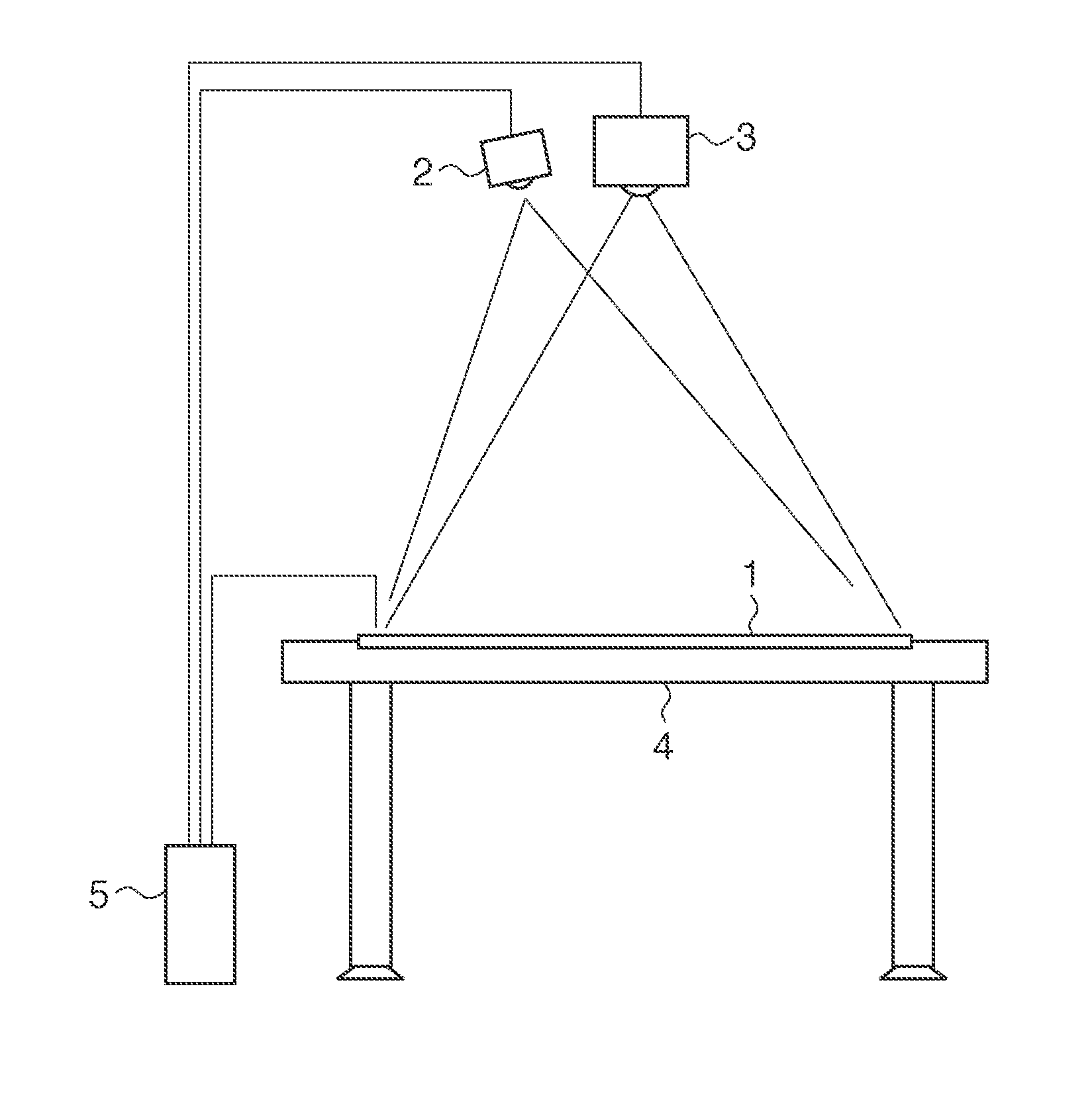
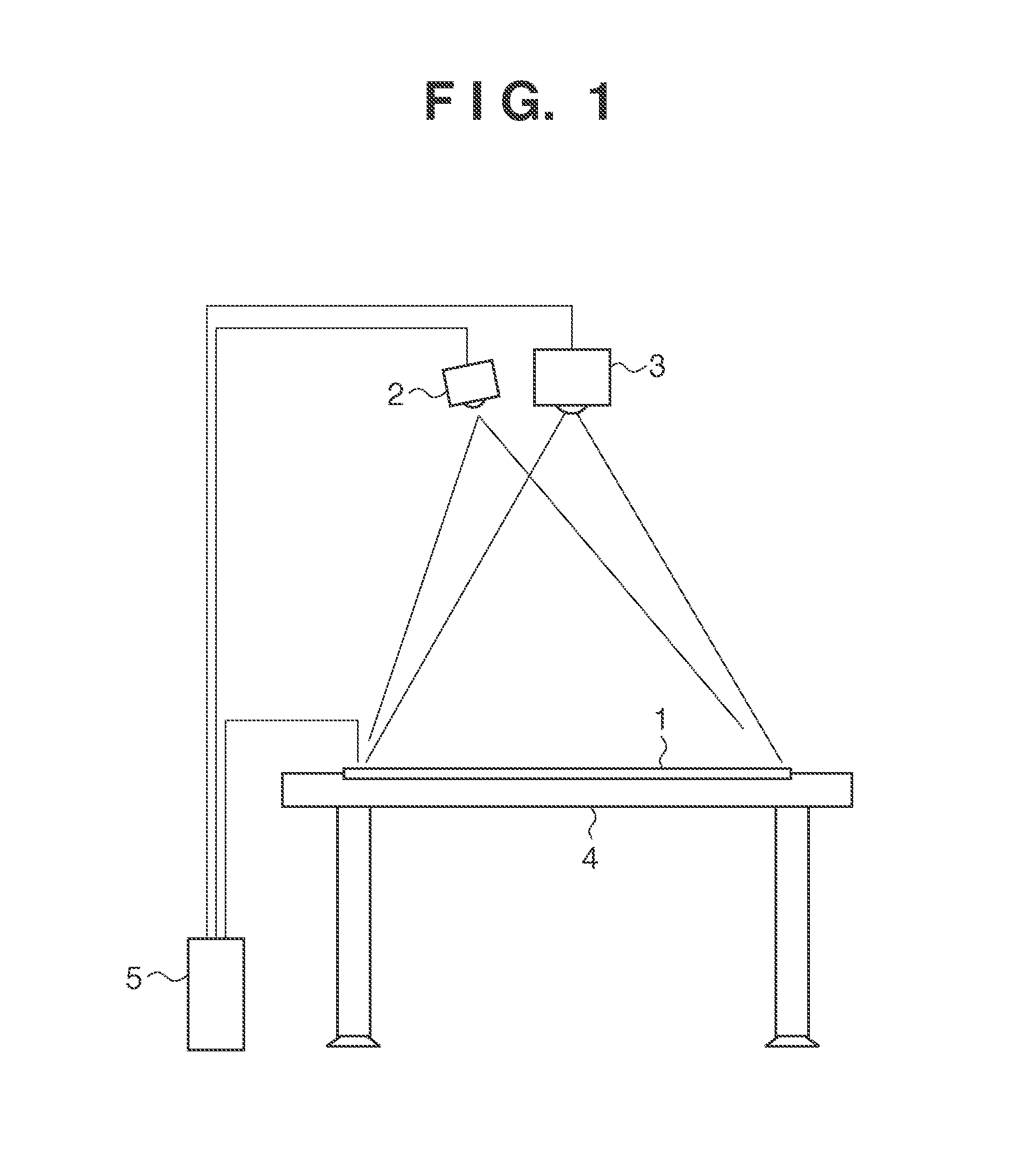
[0028]FIG. 1 shows a schematic view of an information processing apparatus according to the present invention. Although the apparatus according to the present embodiment will become apparent from the following description, the apparatus comprises a construction for displaying at least one selection-target object in a display area having a two-dimensional plane, and a construction serving as the first detecting means for detecting a two-dimensional contact position of a pointer operated by an operator, which is corresponding to the display area, as well as a construction serving as the second detecting means for detecting a three-dimensional position of the pointer, operated by the operator, in the space including a direction perpendicular to the display surface of the display area. By controlling them, the apparatus accurately detects an object intended by a three-dimensional gesture. The following description provides an example.

[0029]The apparatus according to the present embodime...

second embodiment

[0060]In the first embodiment, the host computer 5 receives outputs from the two-dimensional coordinate detecting apparatus 1 and three-dimensional coordinate detecting apparatus 2, controls and manages the outputs to achieve the objective. However, an embodiment is not limited to this; for instance, an embodiment may be configured in a way that the three-dimensional coordinate detecting apparatus 2 receives an output result from the two-dimensional coordinate detecting apparatus 1. More specifically, it may be configured in a way that, when the three-dimensional coordinate detecting apparatus 2 receives, from the two-dimensional coordinate detecting apparatus 1, an output result of coordinates which have been detected based on user's touch on the two-dimensional area (display surface), the three-dimensional coordinate detecting apparatus 2 compares an output result of itself with the received coordinates (three-dimensional coordinate data having 0 as a Z-axis value) or performs ana...

third embodiment

[0061]In the first embodiment, an analysis-start trigger for gesture command generation is an output of the two-dimensional coordinate detecting apparatus 1, and a cancel trigger of the analysis is an output of the three-dimensional coordinate detecting apparatus 2. However, an embodiment is not limited to this; for instance, a certain object (cancel object) may be displayed in the display area for enforcing cancellation.

[0062]Processing in this case is described with reference to FIG. 5. In S301, Flag=0 is set for initialization. In S302, it is determined whether or not an output is acquired from the three-dimensional coordinate detecting apparatus 2. If no object is detected by the three-dimensional coordinate detecting apparatus 2, it is determined whether or not Flag=1 stands (S312). In a case of Flag=0, the control returns to three-dimensional coordinate detection by the three-dimensional coordinate detecting apparatus 2. In a case of Flag=1, as will be apparent from the follow...


PUM


Abstract

According to the present invention, even if a plurality of operators perform gesture operations in three-dimensional space, the three-dimensional spatial gesture of each operator is accurately associated with the target object of the three-dimensional spatial gesture. For this, a projector displays at least one selection-target object on an upper surface of a table. When a pointer operated by an operator comes in contact with the upper surface of the table, a two-dimensional coordinate detecting apparatus detects the contact position, and determines which object has been designated by the operator. In this stage, among pointers detected by a three-dimensional coordinate detecting apparatus, a pointer having a position closest to the contact position is determined, and the pointer determined to be the closest is decided as a tracking target. Thereafter, the tracking-target pointer is tracked by the three-dimensional coordinate detecting apparatus to determine the operator's gesture pattern.

Description

BACKGROUND OF THE INVENTION[0001]1. Field of the Invention[0002]The present invention relates to a technique for performing processing, which corresponds to a user's gesture in three-dimensional space.[0003]2. Description of the Related Art[0004]Conventionally, coordinate input apparatuses that employ various methods have been proposed and put into production. Among them, touch panels are widely used, as they only require a user's finger touch on a display screen and require no special device. A positional detection method employed by this type of apparatus includes a resistive film method, an electrostatic capacity method, an ultrasonic wave method utilizing surface acoustic waves, an optical method, and the like. In a resistive film method, for instance, a change in a resistance value is measured when a finger or the like depresses a plurality of sheets where transparent electrodes are planted, and the depressed position is calculated. Since position calculation is performed by me...

Claims


Application Information

Patent Timeline
Patent Type & Authority Applications(United States)
IPC IPC(8): G06F3/042G06F3/0346G06F3/038
CPCG06F3/017G06F3/04883G06F3/041G06F3/0346G06F3/0425G06F2203/04106G06F2203/04101G06F3/04186
Inventor SATO, HAJIMEKOBAYASHI, KATSUYUKI
Owner CANON KK
Why Eureka
Try Eureka