Three-dimensional image pickup apparatus and lens driving method of three-dimensional image pickup apparatus

a three-dimensional image and pickup apparatus technology, applied in the field of three-dimensional image pickup apparatus, can solve the problems of complicated driving control, deviation of the position of the focusing lens of the first imaging unit and the second imaging unit, and may cause deviation, so as to suppress the deviation of the image center, suppress the dispersion of the angle of view, and reduce the positional deviation of the focusing lens

Inactive Publication Date: 2012-01-26
PANASONIC INTELLECTUAL PROPERTY MANAGEMENT CO LTD
View PDF4 Cites 15 Cited by
  • Summary
  • Abstract
  • Description
  • Claims
  • Application Information

AI Technical Summary

Benefits of technology

[0011]By the first and second aspects, a range of moving the zooming lens and the focusing lens is limited in either one of a first range from a wide-angle end in the tracking curve to a inflection point at which the moving direction of the focusing lens is inverted, and the second range from a telephoto end to a inflection point at which the moving direction of the focusing lens is inverted. Herein, when both of the ranges are used, the moving direction of the focusing lens is inverted when exceeding the inflection point from the wide-angle end or the telephoto end, and the driving control is complicated, and thereby a deviation is likely to occur in the position of the focusing lens of the first imaging unit and the second imaging unit. In the aspects, however, the range of the moving zooming lens and the focusing lens is limited in either one range as mentioned above. As a result, as compared with the case of using the both ranges, it is possible to reduce the positional deviation of the focusing lens when the position of the zooming lens is changed. Accordingly, it is possible to suppress dispersion of the angle of view of the right and left images. It is further possible to suppress the deviation of the image center due to deviation of optical axes of the imaging units.

Problems solved by technology

In the three-dimensional image pickup apparatus having two imaging units, there are problems aside from the aforementioned problems.
For example, there is a problem that a difference is caused between right and left imaging units in the moving amount of the lenses composing two imaging units, and thus a deviation may be caused in the angle of view or image center of the images obtained in two imaging units.
Herein, when both of the ranges are used, the moving direction of the focusing lens is inverted when exceeding the inflection point from the wide-angle end or the telephoto end, and the driving control is complicated, and thereby a deviation is likely to occur in the position of the focusing lens of the first imaging unit and the second imaging unit.
In the aspects, however, the range of the moving zooming lens and the focusing lens is limited in either one range as mentioned above.

Method used


Image

  • Three-dimensional image pickup apparatus and lens driving method of three-dimensional image pickup apparatus
  • Three-dimensional image pickup apparatus and lens driving method of three-dimensional image pickup apparatus
  • Three-dimensional image pickup apparatus and lens driving method of three-dimensional image pickup apparatus

Examples


embodiment 1

1. Configuration of Three-Dimensional Image Pickup Apparatus

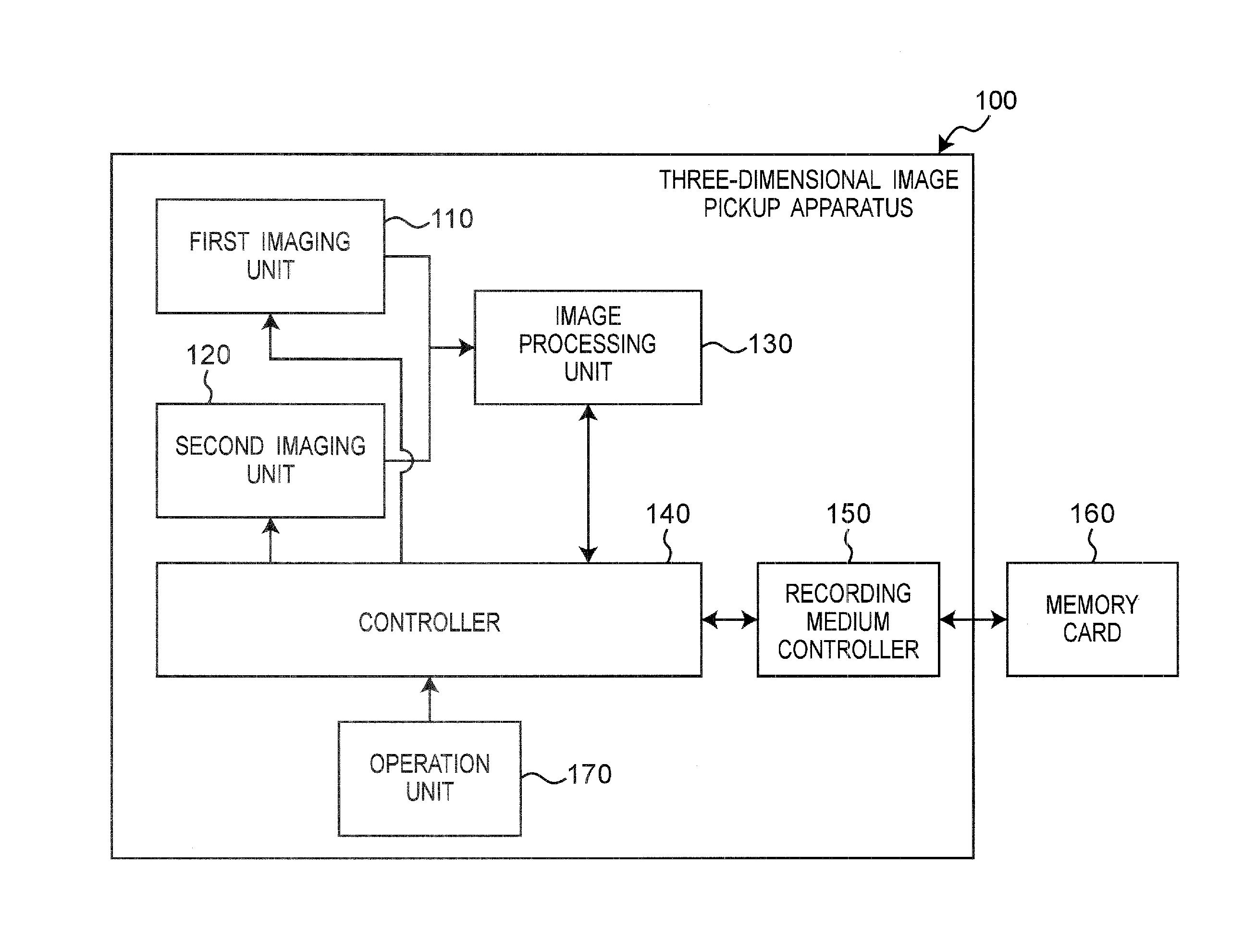
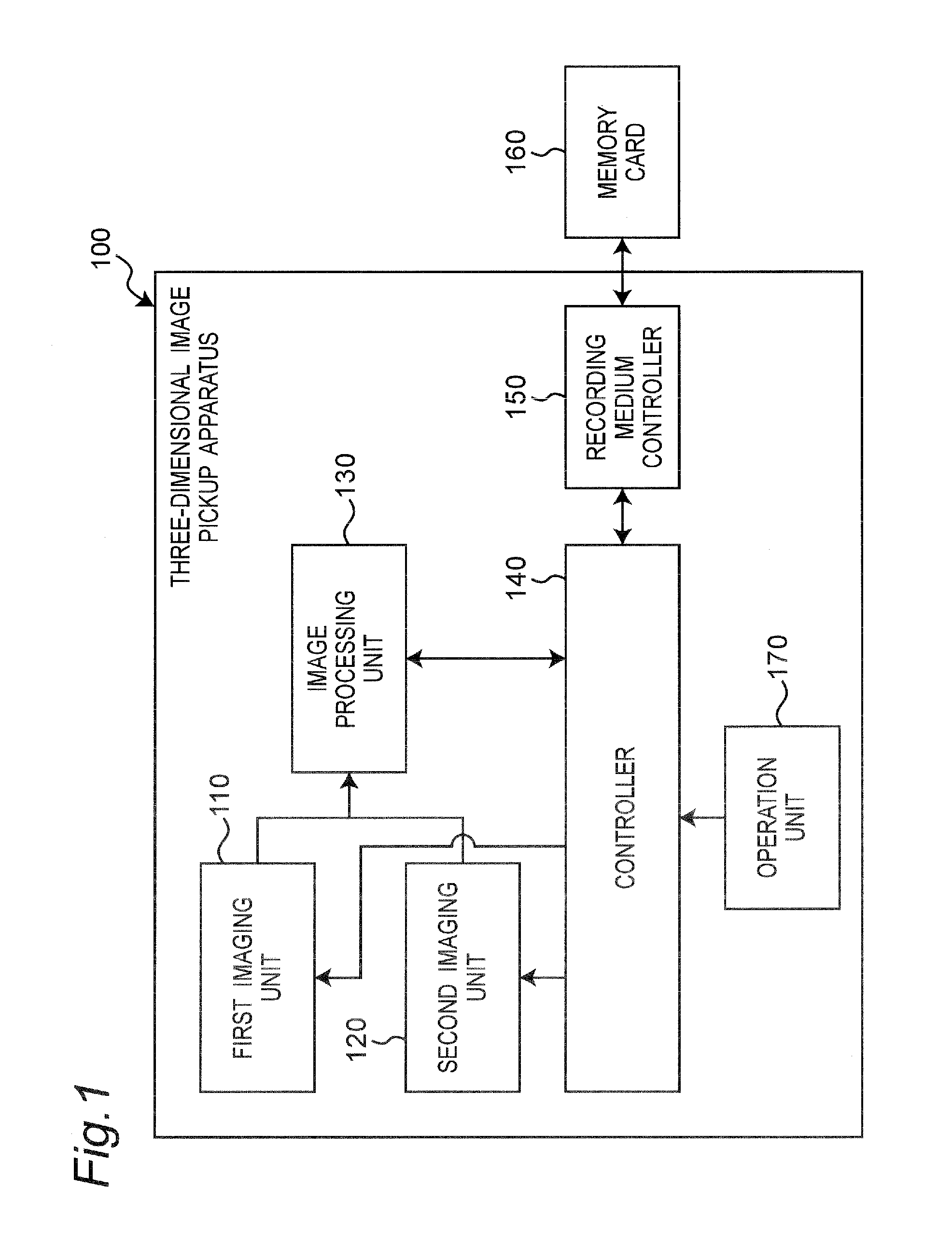
[0021]FIG. 1 is a block diagram showing a configuration of a three-dimensional image pickup apparatus 100 according to embodiment 1. In FIG. 1, the three-dimensional image pickup apparatus 100 includes a first imaging unit 110, a second imaging unit 120, an image processing unit 130, a controller 140, a recording medium controller 150, and an operation unit 170. A memory card 160 can be connected to the recording medium controller 150.

[0022]The first imaging unit 110 and the second imaging unit 120 are disposed with a specified spacing. The specified spacing is preferably set at about 65 mm, which corresponds to an average distance between two eyes of an adult person, but the spacing is not limited to this distance. The right and left images captured by the first imaging unit 110 and the second imaging unit 120 are processed in the image processing unit 130. The image data subjected to image processing is recorded in the me...

embodiment 2

[0054]As embodiment 2, other methods of limiting the movement of the zooming lens and the focusing lens along the tracking curve are explained below.

[0055]The configuration and the operation flowcharts of the three-dimensional image pickup apparatus 100 according to embodiment 2 are same as those in embodiment 1, and detailed description is omitted.

[0056]FIG. 8 shows tracking curves in embodiment 2. In FIG. 8, the controller 140 limits the movement of the zooming lens 220 and the focusing lens 250 in a range up to the zoom position of the inflection point (Pi) on the tracking curve for the distance of the object point which is infinite (curve inf), in all object point distances when performing a zoom operation from the wide end (W end) at the most wide-angle position of the zoom position.

[0057]The inflection points of tracking curves at other object point distances are positioned at the telephoto side (the tele end (T end) side from the inflection point of the tracking curve for the...


PUM


Abstract

A three-dimensional image pickup apparatus for capturing right and left images with a first imaging unit and a second imaging unit to generate a stereoscopic image is provided. In this three-dimensional image pickup apparatus, each of the first imaging unit and the second imaging unit includes a lens group including a zooming lens and a focusing lens, and a imaging device for converting an optical image from the lens group into an electrical signal, and the three-dimensional image pickup apparatus includes a driving controller operable to drive the zooming lens and the focusing lens of the first imaging unit and the second imaging unit, along a tracking curve showing a relationship of a position of the zooming lens and a position of the focusing lens, and the driving controller limits a range of moving the zooming lens and the focusing lens in either one of a first range and a second range, the first range ranges from a wide-angle end in the tracking curve to a inflection point at which the moving direction of the focusing lens is inverted, and the second range ranges from a telephoto end to the inflection point.

Description

BACKGROUND ART[0001]1. Technical Field[0002]The technical field relates to a three-dimensional image pickup apparatus for capturing a three-dimensional image by using two imaging units.[0003]2. Related Art[0004]A pickup apparatus of a three-dimensional image (3D image) has been brought to attention, which is capable of obtaining a stereoscopic image by independently and simultaneously capturing an image for a left eye and an image for a right eye by using two imaging units. Various proposals have been provided for a display device of three-dimensional image or a viewing method thereof, but all of them provide a three-dimensional effect by using binocular disparity.[0005]In such three-dimensional image pickup apparatus, it is important to suppress a deviation of images due to a deviation of optical axes of two imaging units or the like. As a method of correcting such deviation of optical axes, for example, a method is proposed, which corrects the deviation of optical axes by detectin...

Claims


Application Information

Patent Timeline
Patent Type & Authority Applications(United States)
IPC IPC(8): H04N13/02
CPCG02B7/38H04N13/0239G03B2205/0046G03B35/10H04N13/239
Inventor KOKUWA, TAKASHIKUNISUE, KATSUJI
Owner PANASONIC INTELLECTUAL PROPERTY MANAGEMENT CO LTD
Why Eureka
Try Eureka