Projection type image display apparatus

a technology of projection type and image display, which is applied in the direction of optical elements, instruments, optical radiation measurement, etc., can solve the problems of increasing the size of the apparatus, increasing the size of the disc substrate, and insufficient improvement of the lifetime of fluorescent materials, so as to improve the life of the light source using fluorescent materials and increase the size of the apparatus

Active Publication Date: 2012-01-26
MAXELL HLDG LTD
View PDF3 Cites 33 Cited by
  • Summary
  • Abstract
  • Description
  • Claims
  • Application Information

AI Technical Summary

Benefits of technology

[0005]Accordingly, it is an object of the present invention to furnish a projection type image display apparatus for which the lifetime of the light source using fluorescent material is improved without an excessive increase in the size of the apparatus.

Problems solved by technology

According to JP-A-2009-277516, the excitatory light is still continually irradiated on a circular path of the disc substrate and it is insufficient as the improvement in the lifetime of the fluorescent material.
Further, if the excitatory light is irradiated on a position far from the center of the rotation, it is possible to increase the actual area of irradiation; however, there rises a problem that the size of the disc substrate becomes larger and the apparatus increases in size as well.

Method used


Image

  • Projection type image display apparatus
  • Projection type image display apparatus
  • Projection type image display apparatus

Examples


Embodiment Construction

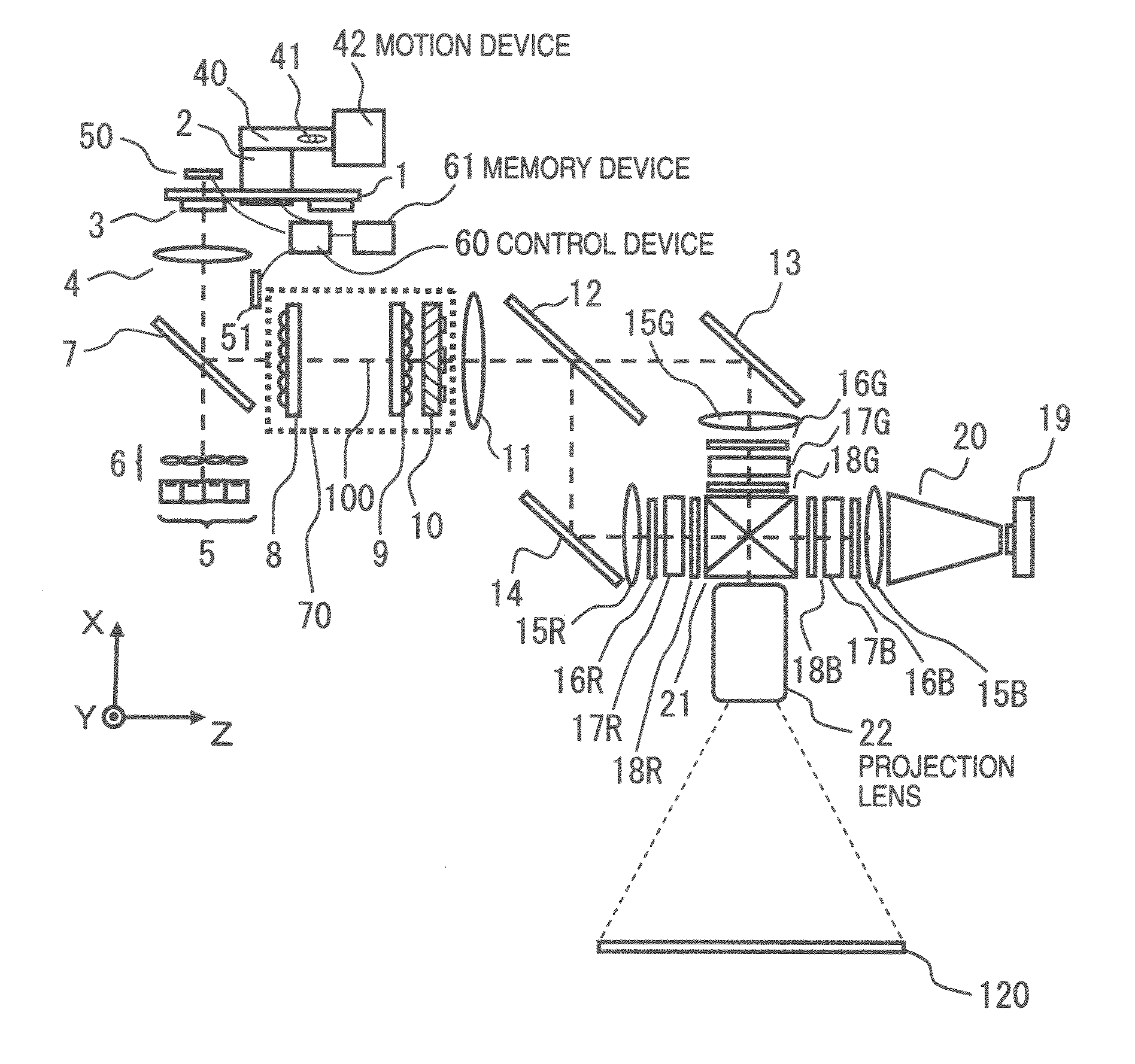
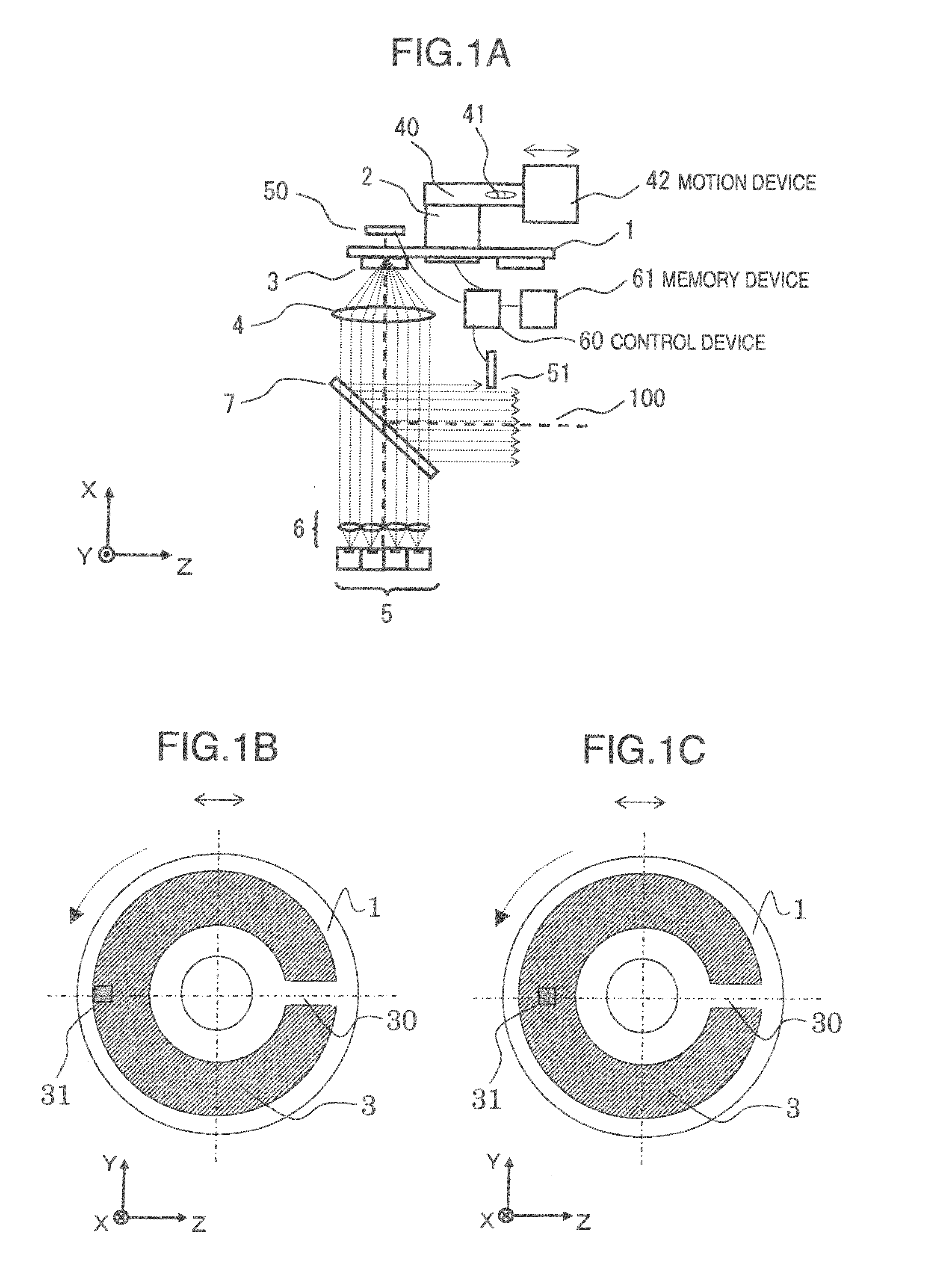
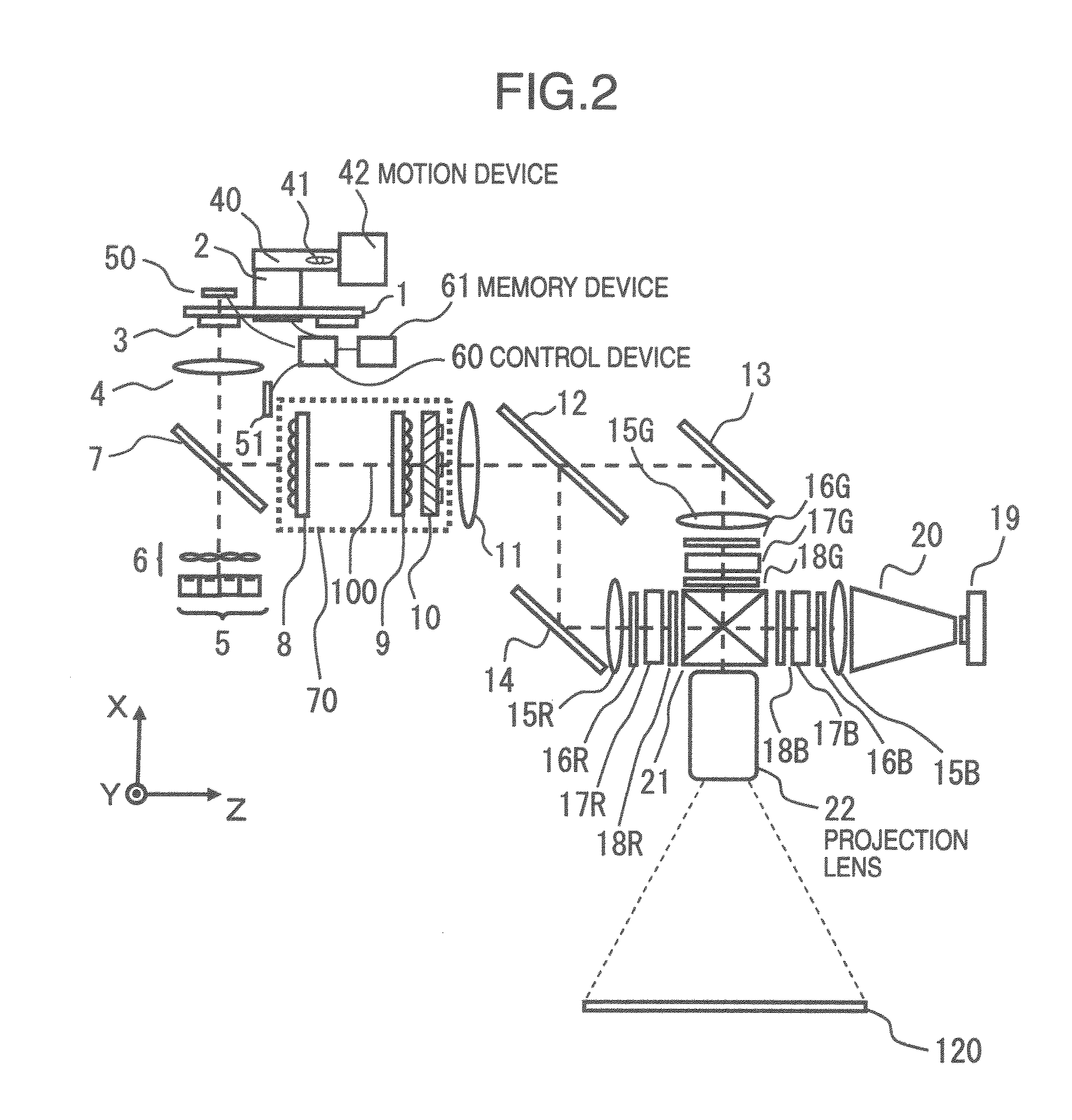
[0012]Hereinafter, an explanation of the present embodiment is given with reference to the drawings. Further, in each diagram, like reference numerals are used to designate like parts and explanations are omitted regarding what have once been explained.

[0013]Here, a right-handed, orthogonal coordinate system is introduced. From the left to the right in a plane of the page is taken to be the Z axis, which falls on the direction of the light on the optical axis 100 in each figure; an axis that is in a plane normal to the Z axis and parallel with the page is taken to be the X axis and an axis that is directed from the back of the page to the front is taken to be the Y axis. (However, regarding FIGS. 1B, 1C, and 3B, the axis directed from the front of the page to the back is taken to be the X axis.) The direction parallel with the X axis is called the “X direction”, the direction parallel with the Y axis is called the “Y direction”, the direction parallel with the Z axis is called the“Z...


PUM


Abstract

A projection type image display apparatus using a light source where excitatory light makes fluorescent material to emit fluorescent light is provided with improved lifetime of a fluorescent material light source without increasing in the apparatus size, The apparatus comprises an excitatory light source cluster, a substrate on which fluorescent material is arranged, light intensity detectors measuring the intensities of the excitatory light and the fluorescent light, a control device which judges based on the measured values of the light intensity detectors whether or not to move the substrate, and a motion device which moves the substrate. The control device may issue an instruction to move the substrate when the ratio of the decrease in the fluorescent light intensity to that in the excitatory light intensity exceeds a prescribed value. Also, the substrate may be moved in a direction perpendicular to the direction of the excitatory light optical axis.

Description

INCORPORATION BY REFERENCE[0001]The present application claims priority from Japanese application JP-2010-163478 filed on Jul. 21, 2010, the content of which is hereby incorporated by reference into this application.BACKGROUND OF THE INVENTION[0002]The present invention pertains to a projection type image display apparatus.[0003]In the concerned technical field, there is proposed a light source apparatus emitting light with high efficiency even if the excitatory light emitted from a solid light source is visible light (JP-A-2009-277516). In JP-A-2009-277516, by irradiating visible light, which has lower energy than ultraviolet, on fluorescent materials as the excitatory light and using the fluorescent materials arranged on a rotationally controlled, circular disc substrate, it is avoided that the excitatory light is irradiated on one spot of the fluorescent material.SUMMARY OF THE INVENTION[0004]According to JP-A-2009-277516, the excitatory light is still continually irradiated on a...

Claims


Application Information

Patent Timeline
Patent Type & Authority Applications(United States)
IPC IPC(8): G03B21/14G01J1/22G02B7/00
CPCG03B21/14G03B21/20H04N9/3155G03B21/2066H04N9/3197G03B21/204G03B21/2053H04N9/3194
Inventor KIMURA, NOBUYUKI
Owner MAXELL HLDG LTD
Why Eureka
Try Eureka