Hand-Held Device and Apparatus Management Method

Inactive Publication Date: 2012-01-26
KONICA MINOLTA BUSINESS TECH INC
View PDF4 Cites 76 Cited by
  • Summary
  • Abstract
  • Description
  • Claims
  • Application Information

AI Technical Summary

Benefits of technology

[0009]Another object of the present invention is to provide a hand-held device and apparatus management m

Problems solved by technology

This has taken time and labor.
This method fails to achieve simple and easy viewing of the statuses of the image forming apparatuses.
However, this method requires underastanding of the positional relationship between the hand-held device and image f

Method used


Image

  • Hand-Held Device and Apparatus Management Method
  • Hand-Held Device and Apparatus Management Method
  • Hand-Held Device and Apparatus Management Method

Examples


example

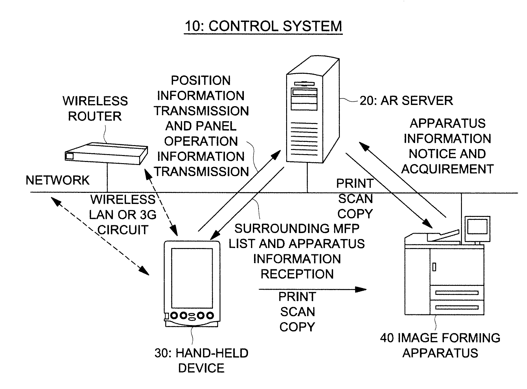
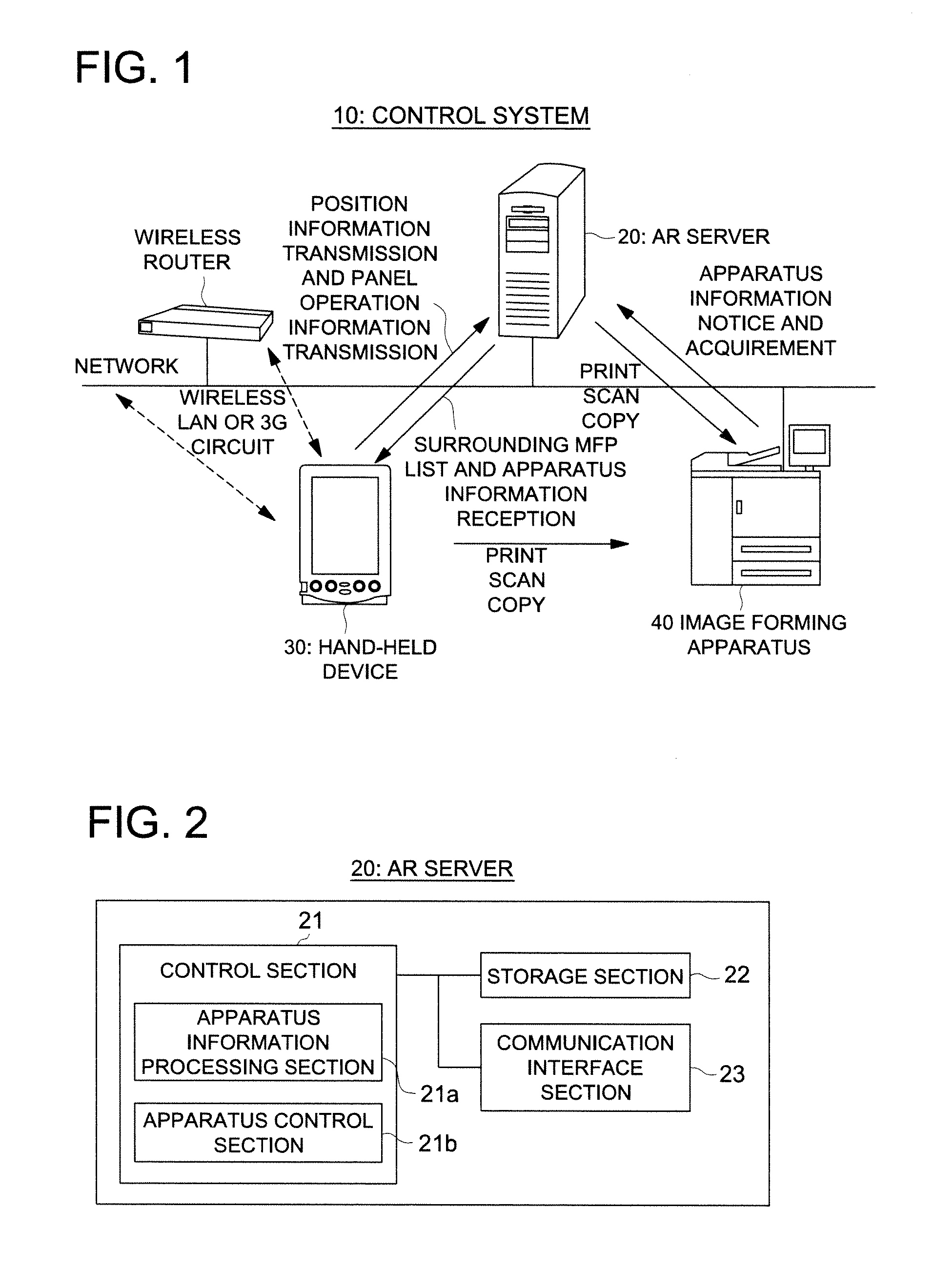
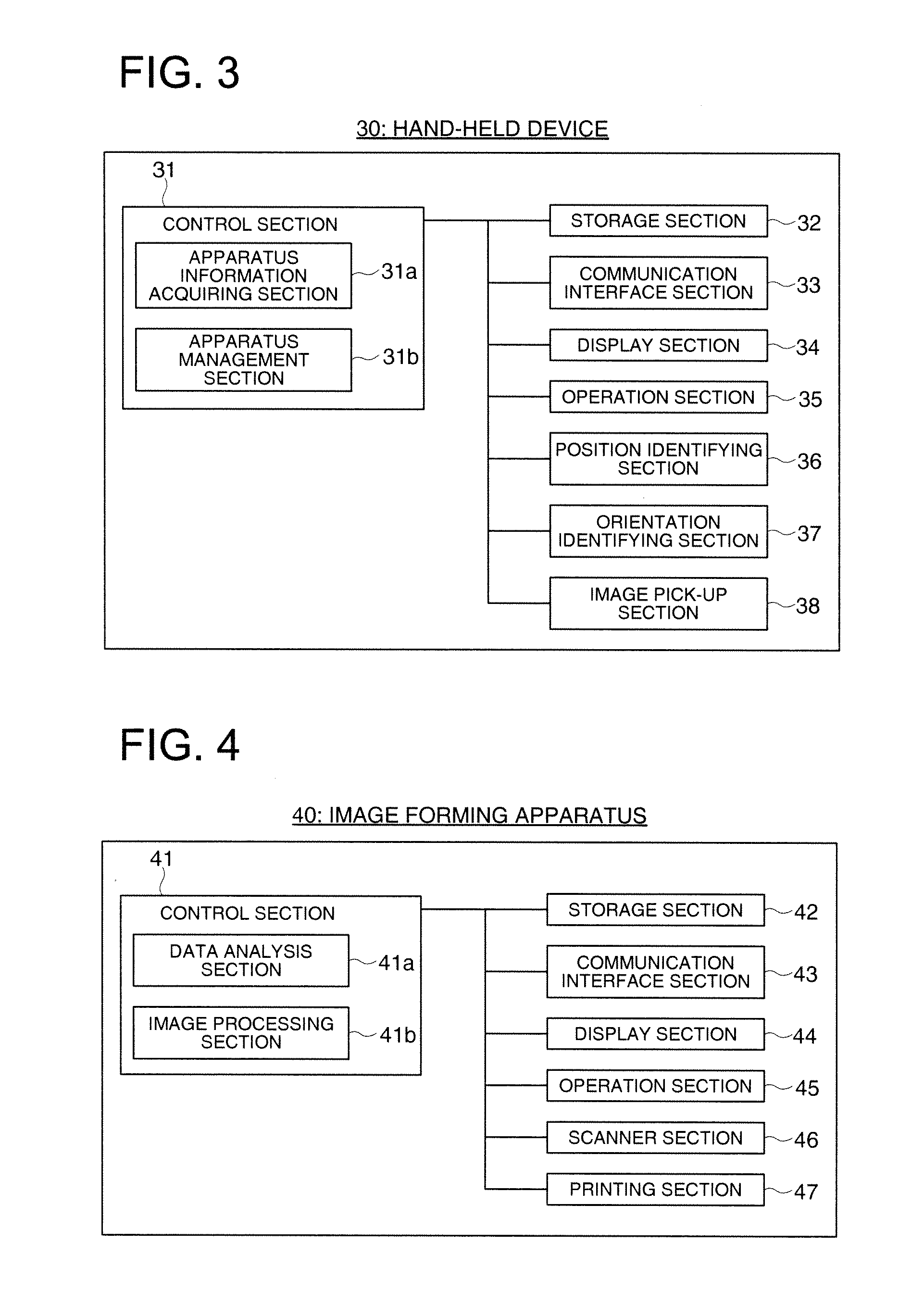
[0037]To describe the further details of the aforementioned embodiment of the present invention, the following describes the hand-held device and apparatus management method related to one example of the present invention with reference to FIGS. 1 through 20. FIG. 1 is a diagram representing an example of the structure of a control system in the present example and FIGS. 2 through 4 are block diagrams representing the structures of the AR server, hand-held device and image forming apparatus. Further, FIG. 5 is a diagram representing the conceptual image of an augmented reality application on the hand-held device. FIGS. 6 through 13 show examples of the hand-held device display screens. FIG. 14 shows an example of the management table data stored in the AR server. FIG. 15 shows the conceptual image of a method for identifying the position of the hand-held device from the intensity of electric field. FIGS. 16a-16c show the method for calculating the position for superimposition of the...


PUM


Abstract

A hand-held device provided with a display section including a position identifying section for identifying the position of a hand-held device; an orientation identifying section for identifying an orientation of the hand-held device; and a control section that specifies a prescribed managed apparatus located within a prescribed range of distance from a hand-held device and in a specific direction of the hand-held device, based on the pre-stored position information on one or plural managed apparatuses, and acquires the status information showing the status of the aforementioned prescribed managed apparatus to display this status information on the display section. Further, an image pick-up section is provided to capture an image in the specific direction. The control section controls the display section to display an image formed by superimposing the aforementioned status information onto the image of the prescribed managed apparatus captured by the image pick-up section.

Description

[0001]This application is based on Japanese Patent Application No. 2010-167424 filed on Jul. 26, 2010 with Japanese Patent Office, the entire content of which is hereby incorporated by reference.BACKGROUND OF THE INVENTION[0002]The present invention relates to a hand-held device and apparatus management method, particularly to a hand-held device having a function of identifying the position and orientation, and a status display and operation method for the image forming apparatus by using the aforementioned hand-held device.[0003]There has been a widespread use of image forming apparatuses (MFPs: Multi Function Peripherals) provided with a copying function, printing function and scanning function. In a business office, a plurality of image forming apparatuses are linked to a network, and the printed copies are given from an image forming apparatus selected by a user.[0004]In such a system, when the image forming apparatus specified by the user is employed by another user, the printi...

Claims


Application Information

Patent Timeline
IPC IPC(8): G06F3/12G06F3/048G06F3/0484
CPCH04N1/00344H04N2201/0027H04N2201/0075H04N2201/0043H04N2201/0055H04N2201/0036
Inventor SATO, TOMONORI
Owner KONICA MINOLTA BUSINESS TECH INC
Why Eureka
Try Eureka