
Zoom lens, and imaging apparatus incorporating the same

Active Publication Date: 2012-01-26
OM DIGITAL SOLUTIONS CORP
View PDF0 Cites 37 Cited by
  • Summary
  • Abstract
  • Description
  • Claims
  • Application Information

AI Technical Summary

Benefits of technology

[0040]By adoption of the positive power-leadoff type zoom lens where the lens group of positive refracting power is located on the most object side, it is possible to design a lens arrangement preferable as a telephoto zoom lens because it works in favor of making sure the desired zoom ratio and the desired brightness at the telephoto end. Substantial zooming takes place by a separation change between the first and the second lens group and a separation change between the second and the third lens group. In addition, the provision of the fourth lens group of negative refracting power allows the size of the first, second and third lens groups to remain small, working in favor of setting up a small-format, less costly zoom lens.
[0220]According to the present invention, there can be a zoom lens provided, which is of small-format size and well fit for the taking of moving images.

Problems solved by technology

This wobbling function requires very fast operation depending on frame rates; so there is still mounting demand for reducing the weight of a lens used for wobbling.
Accordingly, it is controlled such that any out-of-focus state during wobbling cannot be recognized; however, when there is a large image magnification change, images look quite unnatural because they look as if they were always waving.
Further, as there is a large change in the focus sensitivity (the amount of movement of the image plane per unit amount of movement of the lens) of the wobbling lens during zooming, it gives rise to a large difference in the amount of movement required for the wobbling lens at the wide-angle and telephoto ends, resulting in difficulty in control of fast and minute movement.
However, the zoom lens set forth in Patent Publication 1 is far away from being suitable for the taking of moving images because of too large image magnification changes during wobbling.
In the zoom lenses set forth in Patent Publications 2 and 3, there is a fairly large number of lens groups used, which is apt to result not only in the need for using a lot more lenses, but also in bulkier size and higher costs.
Referring again to the zoom lenses disclosed in Patent Publications 4 and 5, the taking of moving images is factored out, so intentional wobbling would result in large magnification changes and the inability to take moving images.

Method used


Image

  • Zoom lens, and imaging apparatus incorporating the same
  • Zoom lens, and imaging apparatus incorporating the same
  • Zoom lens, and imaging apparatus incorporating the same

Examples


example 1-1

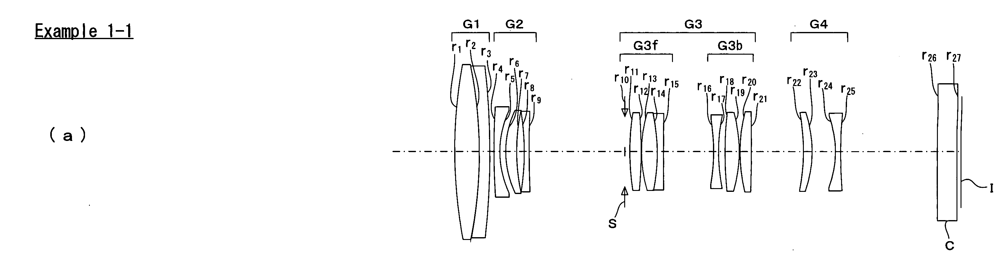
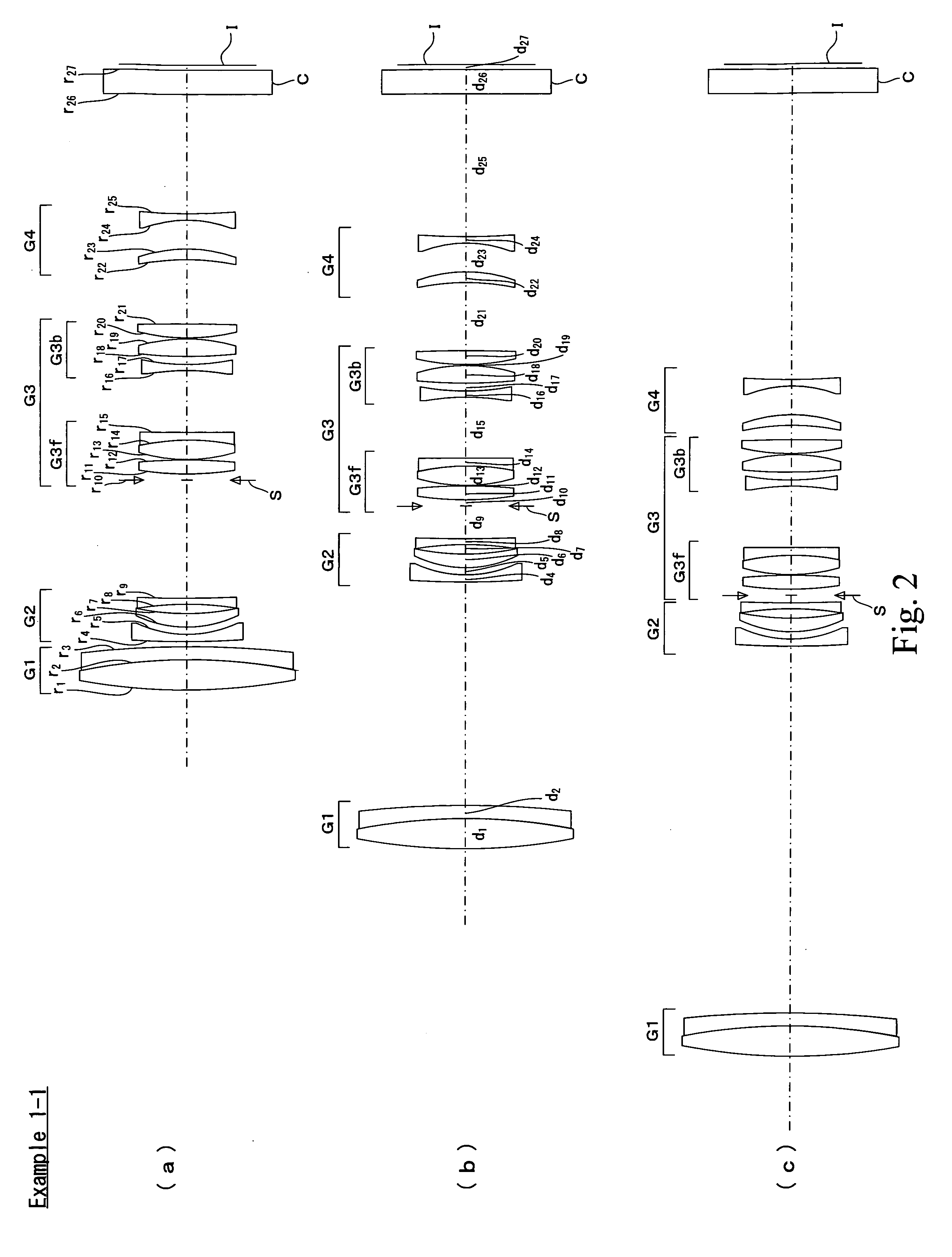
[0249]FIG. 2 is a sectional view of the zoom lens of Example 1-1. As shown in FIG. 2, the zoom lens of Example 1-1 is built up of, in order from the object side to the image side, a first lens group G1 of positive refracting power, a second lens group G2 of negative refracting power, a third lens group G3 of positive refracting power, and a fourth lens group G4 of negative refracting power. In FIG. 2, I and C are indicative of an image plane and a cover glass, respectively.

[0250]The first lens group G1 is made up of a cemented lens of a positive lens and a negative lens.

[0251]The second lens group G2 is made up of, in order from the object side to the image side, a negative lens, a positive lens and a negative lens.

[0252]The third lens group G3 is made up of, in order from the object side to the image side, a stop S, a front unit G3f consisting of a positive lens and a cemented lens of a positive lens and a negative lens, and a rear unit G3b consisting of a negative lens, a positive...

example 1-2

[0259]FIG. 3 is a sectional view of the zoom lens of Examples 1-2. As shown in FIG. 3, the zoom lens of Example 1-2 is built up of, in order from the object side to the image side, a first lens group G1 of positive refracting power, a second lens group G2 of negative refracting power, a third lens group G3 of positive refracting power, and a fourth lens group G4 of negative refracting power. In FIG. 3, I and C are indicative of an image plane and a cover glass, respectively.

[0260]The first lens group G1 is made up of a cemented lens of a positive lens and a negative meniscus lens.

[0261]The second lens group G2 is made up of, in order from the object side to the image side, a cemented lens of a negative lens and a positive lens, and a negative lens.

[0262]The third lens group G3 is made up of, in order from the object side to the image side, a stop S, a front unit G3f consisting of a positive lens and a cemented lens of a positive lens and a negative lens, and a rear unit G3b consisti...

##meral example 1-1

Numeral Example 1-1

[0272]

Surface No.rdndνd 187.8055.0001.5163364.14 2−87.8052.1001.7847225.68 3−178.563 d3 (Variable) 4107.0591.1301.7291654.68 518.7231.247 619.7542.2051.8466623.78 740.8301.481 8−47.2391.0201.7880047.37 9340.768 d9 (Variable)10 (Stop)∞0.9001136.6692.2761.4970081.5412−101.1340.1501326.3523.1701.4874970.2314−39.1311.2001.9108235.2515401.57010.124 16−40.8840.9501.8340037.161733.7931.2771863.4062.9731.6031160.6419−25.0580.1502035.6942.2901.7725049.6021−128.815d21 (Variable)22−37.4151.7001.5927035.3123−22.3814.70024−19.3901.0001.6031160.642586.781d25 (Variable)26∞4.0001.5163364.1427∞0.800Image PlaneData Set 1WESTTEFocal length40.80477.526147.015Fno4.084.455.872ω (°)30.4115.698.30Image Height10.8210.8210.82BF22.81926.66749.994d30.80036.33660.036d919.2515.3001.022d2110.47310.9572.294d2519.38023.22846.555Data Set 2f1139.30f2−35.21f329.05f4−38.89


PUM


Abstract

The invention provides a zoom lens, characterized by comprising, in order from an object side thereof,a first lens group of positive refracting power,a second lens group of negative refracting power,a third lens group of positive refracting power, anda fourth lens group of negative refracting power,upon zooming from a wide-angle end to a telephoto end of the zoom lens,a separation between the respective lens group changes,a separation between the first lens group and the second lens group becomes narrow, anda separation between the second lens group and the third lens group grows wide;upon focusing from a focusing-on-infinity state to a close-range focusing state,the fourth lens group moves in an optical axis direction; andConditions (1) and (2) are satisfied at the wide-angle end.

Description

BACKGROUND OF THE INVENTION[0001]So far, some digital camera products have been known to be capable of taking moving images. In recent years, interchangeable type digital cameras, especially an interchangeable lens compatible with the function of the camera body of taking moving images have also been under study.[0002]Only the requirement for conventional cameras designed to take still images has been that they are in focus on target subjects in the moment of image shooting after determination of the composition, because their object has been not to miss blink-of-an-eye shutter chances. For instance, the so-called autofocus (AF) function has been adopted because of its combined high speed / accuracy.[0003]In the taking of moving images with some video cameras designed for professional use, on the other hand, a skilled cameraman has implemented focusing operation in the manual focus (MF) mode. For many consumer-oriented video cameras, however, it is required to put the AF system consta...

Claims


Application Information

Patent Timeline
IPC IPC(8): G02B15/14
CPCG02B13/04G02B15/173G02B15/177G02B15/144105G02B15/144511
Inventor OGATA, YASUJIYAMADA, YASUHARUKASHIKI, YASUTAKATAKAHASHI, TOSHIOKON, TOYOKI
Owner OM DIGITAL SOLUTIONS CORP
Features
  • Generate Ideas
  • Intellectual Property
  • Life Sciences
  • Materials
  • Tech Scout
  • Unparalleled Data Quality
  • Higher Quality Content
  • 60% Fewer Hallucinations
Learn More