
Synthetic instrument unit

a technology of synthetic instruments and instruments, applied in the direction of transmission monitoring, amplitude demodulation, digital transmission, etc., can solve the problems of inability to meet the needs of the user

Active Publication Date: 2012-01-26
BAE SYST INFORMATION & ELECTRONICS SYST INTERGRATION INC
View PDF8 Cites 34 Cited by
  • Summary
  • Abstract
  • Description
  • Claims
  • Application Information

AI Technical Summary

Benefits of technology

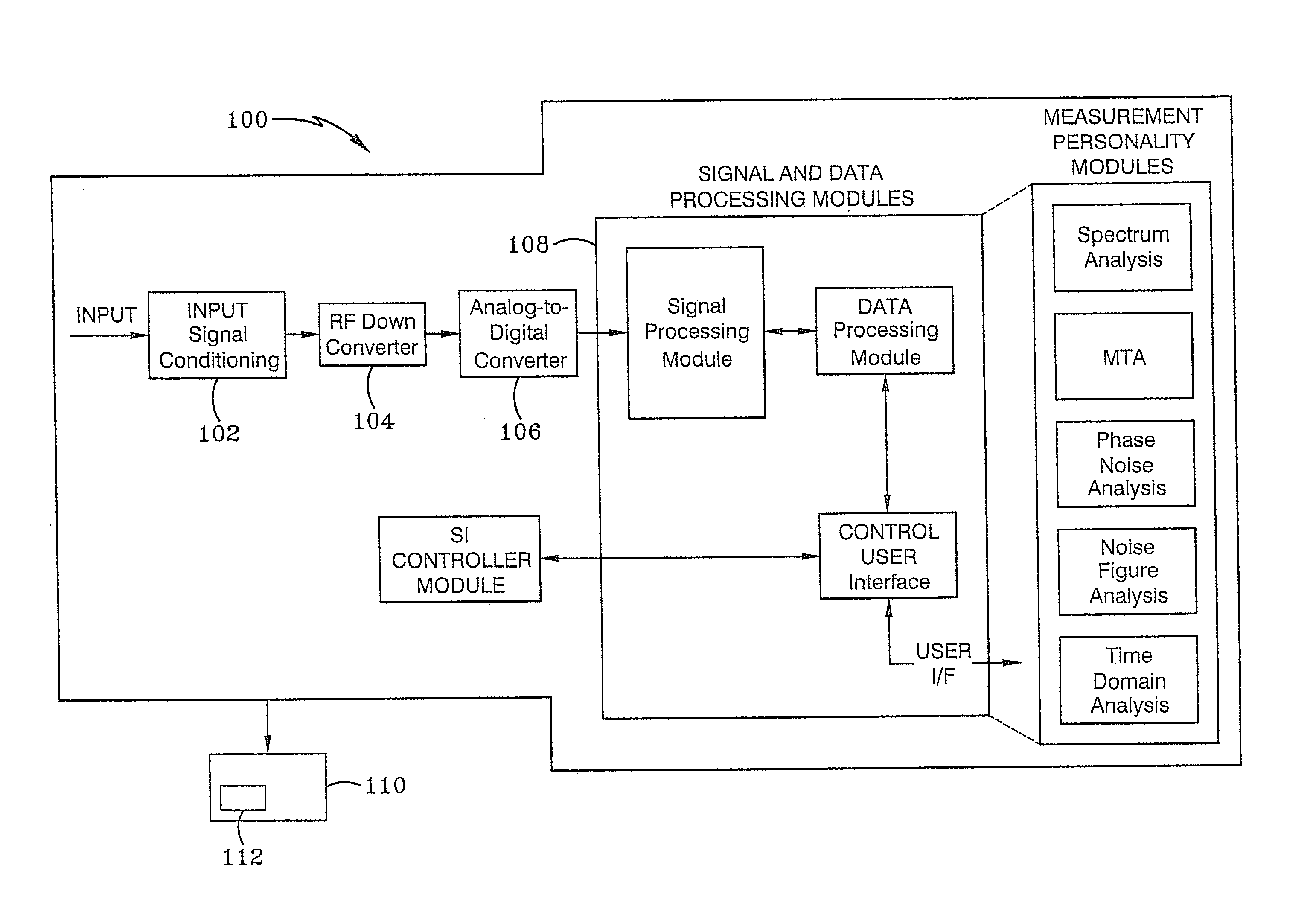
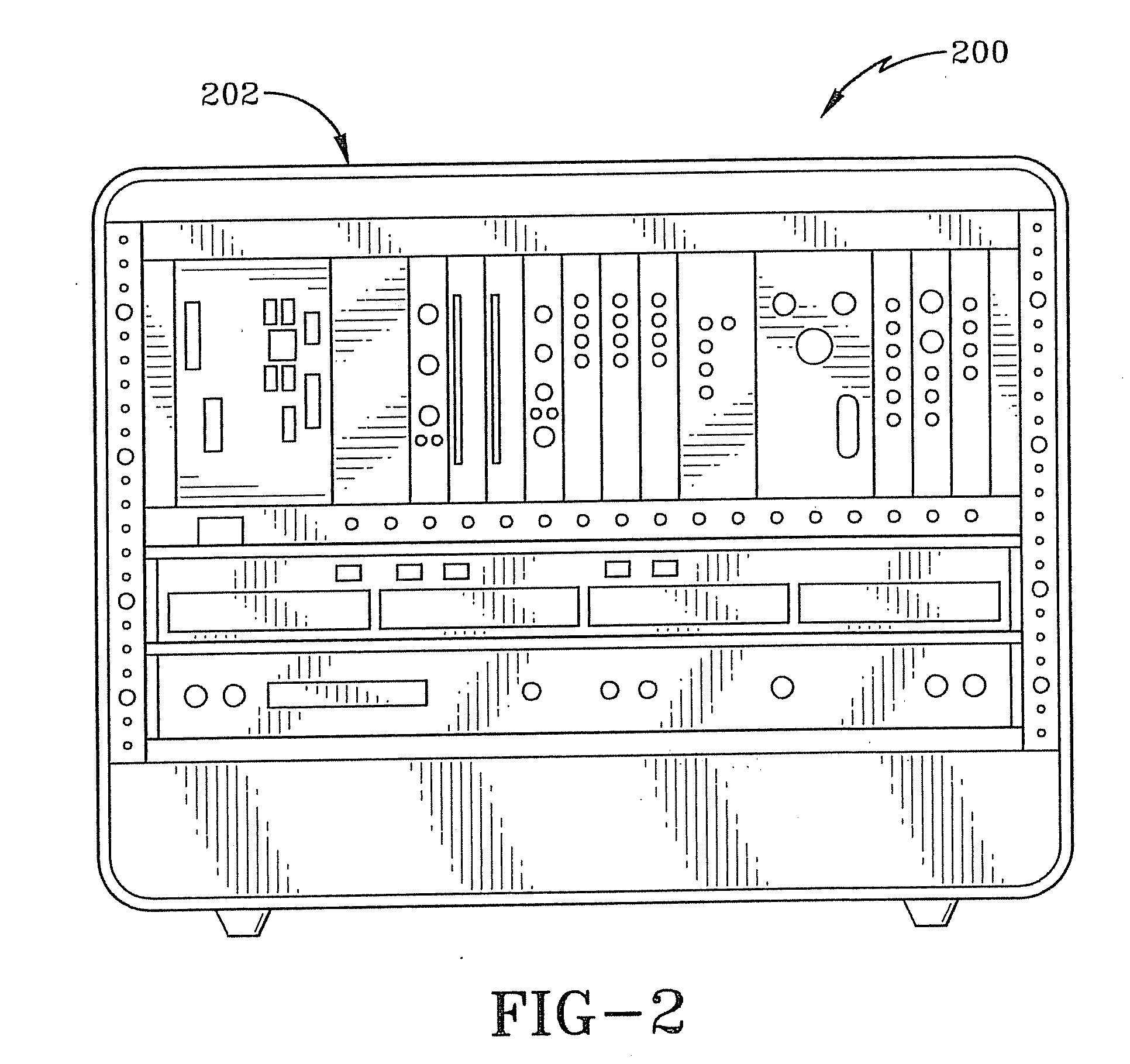
[0008]In another configuration, the synthetic instrument unit can be mounted within an extension for Instrumentation (PXI) Express chassis with at least one peripheral component interconnect PCI Express bus. The synthetic instrument unit is coupled to the PCI Express bus. A bridge can couple the PXI Express chassis to the synthetic instrument unit for remote communication and control of the synthetic instrument unit. The SIU can include an embedded controller supporting real-time control of the PXI chassis. The embedded controller can further comprise a removable hard drive with memory accessible by the synthe

Problems solved by technology

This dynamic situation often results in a mismatch between the operational units to be supported in the field and the test support systems required to RFI and diagnose these systems.
This situation has often resulted in inflexible, redundant, and costly hardware centric solutions that are often both difficult to support and prone to obsolescence due to the “technology gallop” previously mentioned.
In fact, the greatest challenge to the eCASS program is its ability to both satisfy legacy support requirements while at the same time keep in sync with and satisfying future / emerging requirements, in order to keep eCASS technically viable and relevant going forward.
This is a daunting challenge, especially in the RF / MW arena where the testing requirements can often be complex and exacting.

Method used


Image

  • Synthetic instrument unit
  • Synthetic instrument unit
  • Synthetic instrument unit

Examples


Embodiment Construction

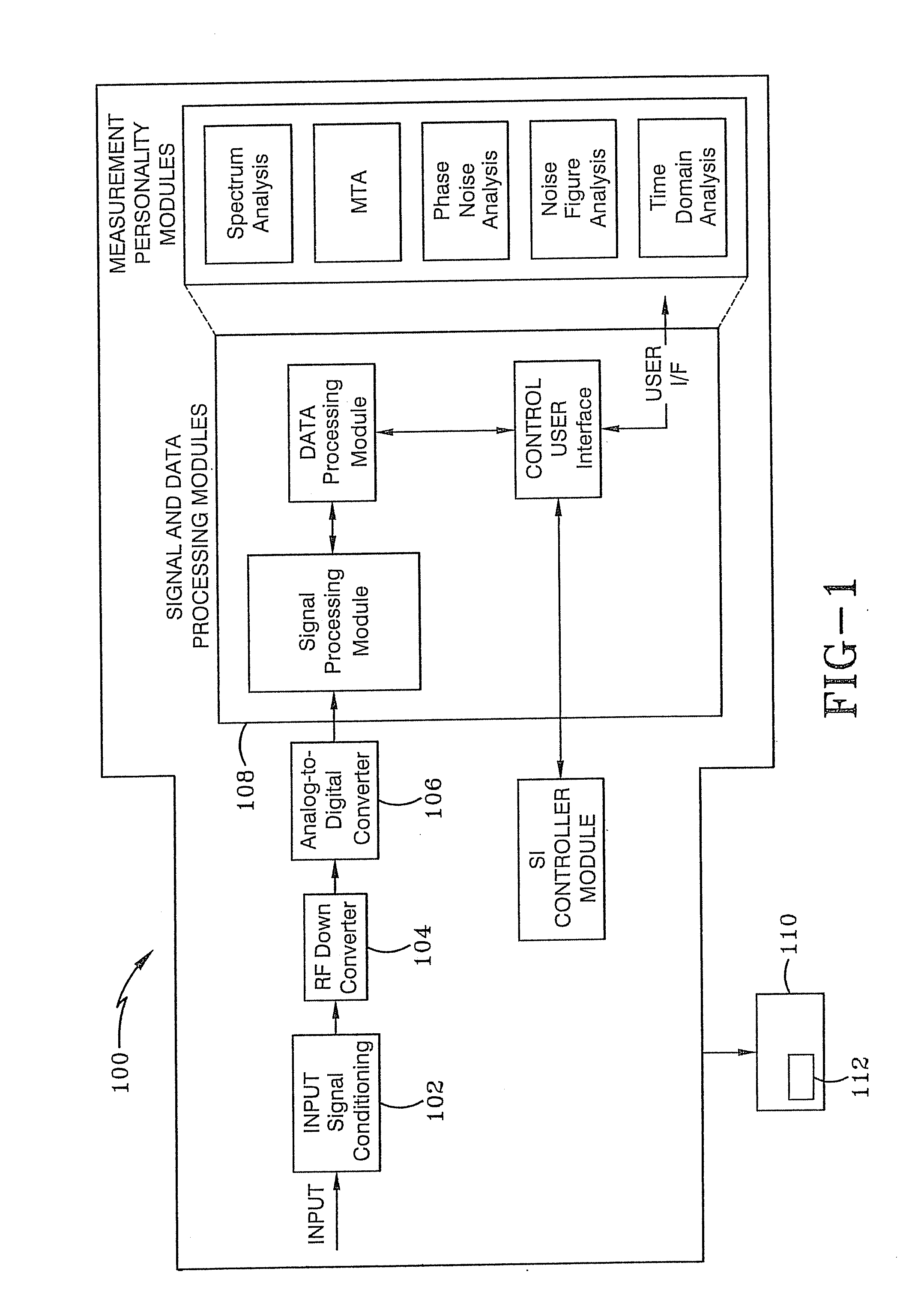
[0029]RF measurements capability based on synthetic instrumentation technology can be a solution for the next-generation eCASS ATE due to the flexibility of synthetic instruments to adapt to uncertain and future test requirements. Synthetic instrumentation (SI) can readably adapt to new test requirements because an SI synthesizes the measurement functionality found in traditional instruments via employing a combination of core hardware and Digital signal processing (DSP) software building blocks in a modular open architecture environment. Synthetic instruments are substantially different from classical instruments in that the measurement functions are synthesized from a limited set of “generic” SI components as opposed to discrete instrument types, such as a spectrum analyzer. Users typically interact with a SI via a software-defined Graphical User Interface (GUI) which simulates a front panel for an entire SI, or its constituent components, by providing software “widgets” that emul...


PUM


Abstract

Systems and other embodiments associated with synthetic instrumentation are presented. A reconfigurable synthetic instrumentation unit comprises an input module, with dual input / output ports and conditioning logic to condition an input signal. An RF down converter selectively down converts the conditioned input signal. A sampled RF down converter selectively samples the conditioned input signal. A pair of narrowband A / D converters are configured to convert one of the conditioned signal, the down converted signal and the sampled signal to produce a narrowband digital signal. A pair of broadband A / D converters convert at least one of the conditioned signal, the down converted signal and the sampled signal to produce a broadband digital signal. Signal processing logic selectively performs digital signal processing on the broadband digital signal or the narrow band digital signal.

Description

BACKGROUND OF THE INVENTION[0001]1. Technical Field[0002]The present invention relates generally to apparatus, methods and systems for testing electronic equipment. More particularly, the apparatus, methods and systems related to synthetic instruments for testing electronic equipment. Specifically, the apparatus, methods and systems of the present invention relate to synthetic instruments based vector network analyzer for testing electronic equipment.[0003]2. Background Information[0004]The previous generations of aviation support equipment dating back over the past forty years (i.e., VAST, CASS) show that continuous change in avionics and test technology is inevitable. “Technology gallop” as well as the changing mission landscape in terms of units under test (UUTs) to be supported in the future is ever changing. This dynamic situation often results in a mismatch between the operational units to be supported in the field and the test support systems required to RFI and diagnose thes...

Claims


Application Information

Patent Timeline
IPC IPC(8): H04B17/00
CPCG01R23/16G01R19/2516
Inventor ESTRADA, ANTHONY J.FORD, DANA C.KIM, TAE S.LOWDERMILK, ROBERT W.VULETIC, DRAGAN
Owner BAE SYST INFORMATION & ELECTRONICS SYST INTERGRATION INC
Learn More