Housing for a ball joint

a ball joint and housing technology, applied in the direction of couplings, rod connections, mechanical devices, etc., can solve the problems of moisture and impurities entering the interior of the joint, the sealing bellows edge detachment from the fixed position of the housing, and the deformation of the already deformed section, etc., to achieve the effect of reducing the overall manufacturing process, reducing the risk of slipping, and improving the sealing

Inactive Publication Date: 2012-01-26
ZF FRIEDRICHSHAFEN AG
View PDF9 Cites 4 Cited by
  • Summary
  • Abstract
  • Description
  • Claims
  • Application Information

AI Technical Summary

Benefits of technology

[0018]Optimum sealing can be created due to this contact for the sealing bellows edge located roughly in the center of the housing. The tensile stress acting on the sealing bellows due to the pivoting of the ball journal on the sealing bellows and / or the torsion applying stress on the sealing bellows can be compensated in this way. In this regard the sealing bellows has a length which allows it to be designed in a helical shape having a plurality of pleats, such that it can compensate for the movements due to the inherent elasticity thereof and does not detach from the contact region thereof.
[0019]If the contact region for the sealing bellows edge is provided roughly at the level of the center of the joint ball, it is particularly advantageous for radial joints. Radial joints of this kind usually have a shaft which protrudes laterally from the housing and is used to connect the housing later to corresponding components. This shaft running radially with respect to the longitudinal axis of the non-deflected ball journal directly adjoins the contact region for the sealing bellows edge. It was found that due to the claimed design of the housing, the connection of the shaft in radial joints is associated with smaller flexural stresses under load. This represents an additional, very important advantage of the embodiment described herein.
[0020]In the course of the simplification of the overall manufacturing process for a claimed housing for a ball joint, an additional proposal is that the housing as a whole is produced by a cold extrusion method or by a forging process. When using a cold extrusion method, advantageously all process steps for producing the housing can be implemented in sequence, without requiring any power-consuming heating of the material.
[0021]However, the forging process has the advantage that although it is indeed more energy-intensive, the production of the housing is possible with tighter component tolerances. In the case of a hot forged housing, it is even possible to produce the contact region for the sealing bellows edge and / or the deformed section during forging, thereby requiring no finishing any longer. Likewise, this result can also be achieved by a calibration process. But in such cases, subsequent machining is indispensible.
[0022]Moreover, at least the contact region for the sealing bellows edge and / or the deformed section of the housing produced by a forging process can be a subsequently machined section. Due to the subsequent machining of individual sections of the housing, a housing produced in this manner can be created with tight tolerances and lower consumption of materials. In addition, housings produced by a forging process have high component strength and due to the material properties thereof, allow good deformability.

Problems solved by technology

If a contact region for the sealing attachment of the sealing bellows edge, and also a deformed section for the rotationally and pivotably movable fixation of the joint ball of the ball journal in the interior space of the housing to the opening side of the housing are both provided on a housing for a ball joint, then the disadvantage results in the potential that the sealing bellows edge detaches from the fixed position thereof at the housing and slides across the already deformed section.
However, any mobility of the sealing bellows edge means that the sealed contact of the sealing bellows edge against the housing is no longer ensured in a reliable manner in every case, and thus the danger exists that moisture and impurities can penetrate into the interior of the joint.
Damage to the joint components resulting in this manner can ultimately lead to complete failure of the ball joint.

Method used


Image

  • Housing for a ball joint
  • Housing for a ball joint
  • Housing for a ball joint

Examples


Embodiment Construction

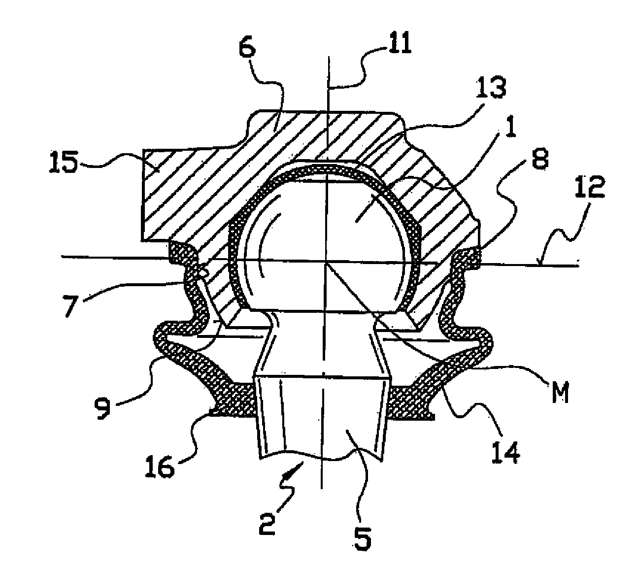
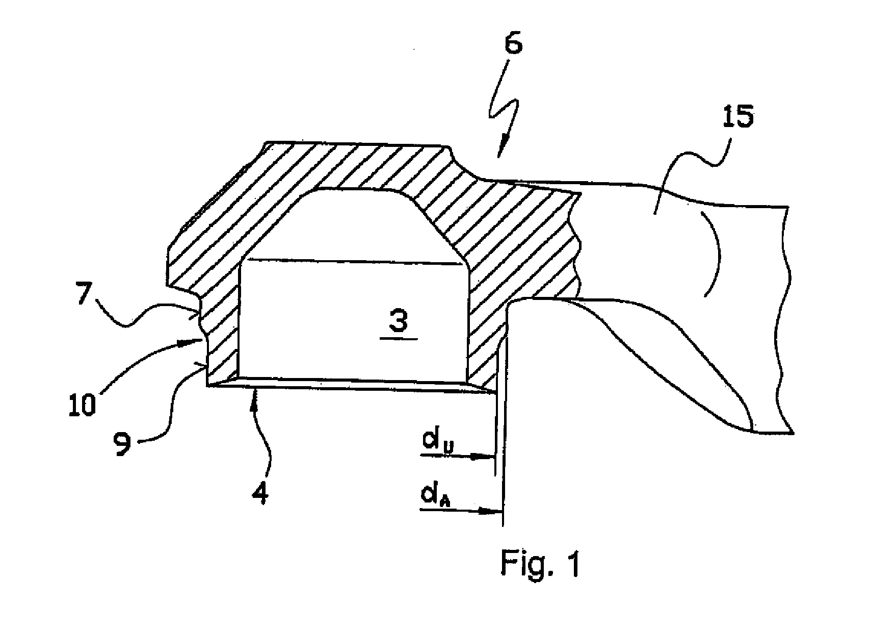
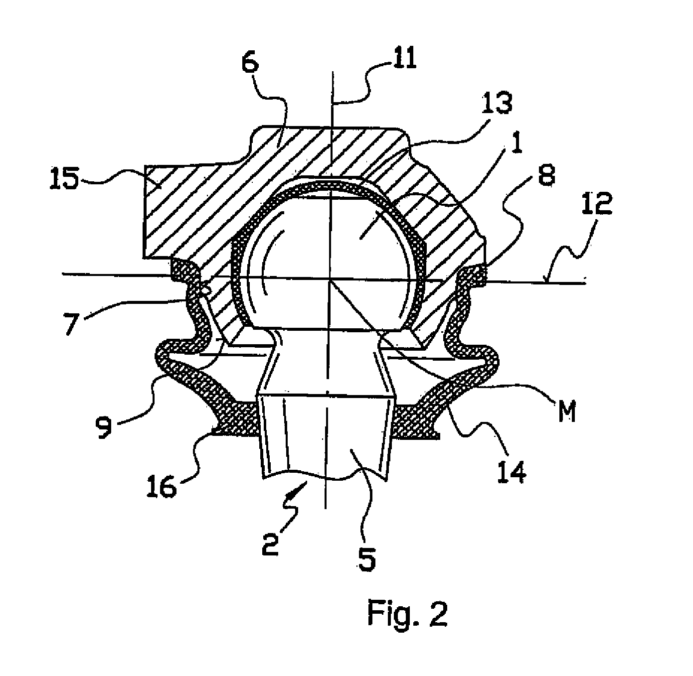
[0027]The housing illustrated in FIG. 1 and denoted overall by reference number 6 has a shaft 15 by which the housing 6 can be attached to a corresponding component. In the housing 6, an interior space 3 is present, the configuration of which allows accommodation of the joint ball of a ball journal, and also of a bearing shell supporting this joint ball. The special embodiment of a housing 6 according to the illustration in FIG. 1 is designed as a housing 6 open on one side. Accordingly, the housing 6 has an opening 4. During installation of the ball joint, an assembly comprising the ball journal and the bearing shell placed onto the joint ball of the ball journal, can be introduced through this opening 4 into the housing 6. In the region on the opening side, the housing 6 first has a contact region 7 for the sealing contact of a sealing bellows edge. The contact region 7 is designed in this case as a circular cylindrical contact surface and consequently has a diameter dA. Viewed in...


PUM


Abstract

A housing component for a ball joint has an interior space (3) adapted for mounting the joint ball (1) of a ball journal, an opening (4) for guiding the journal section (5) of the ball journal (2) adjoining the joint ball (1), a contact region (7) formed on an outer lateral surface of the housing (6) for fastening a sealing bellows edge (8) and forming a seal, and a deformed section (9) which rotationally and pivotally fixes the joint ball (1) of the ball journal (2) in the interior space (3) of the housing (6). The deformed section (9) has a smaller material cross-section in comparison to the contact region (7) for the sealing bellows edge (8).

Description

[0001]This application is a National Stage completion of PCT / DE2008 / 050019 filed Jul. 30, 2008 which claims priority from German patent application Ser. No. 10 2007 038 492.2 filed Aug. 14, 2007.FIELD OF INVENTION[0002]The invention relates to a housing for a ball joint according to the preamble of claim 1.BACKGROUND OF THE INVENTION[0003]A method is known from DE 195 36 035 A1 for the production of a housing for a ball joint, in particular for tie rods of motor vehicles, and a housing for a ball joint produced by this method. The housing has an interior space adapted for mounting the joint ball of a ball journal and also an opening for guiding through the journal section of the ball journal adjoining to the joint ball. The housing is open on both sides and on one side is closed by a cover, wherein a deformed section is provided at the upper edge of the housing for fixing the cover. The closure is affected by means of a cover after the ball journal was inserted into the interior spa...

Claims


Application Information

Patent Timeline
Patent Type & Authority Applications(United States)
IPC IPC(8): F16C11/06
CPCF16C11/0623Y10T403/31Y10T403/32672Y10T403/32631F16C11/0633F16C11/0685
Inventor SCHMITZ, JURGENSCHMEINK, FRANK
Owner ZF FRIEDRICHSHAFEN AG
Why Eureka
Try Eureka