Variable Transition Pressure Profiles for a Bi-Level Breathing Therapy Machine

a transition pressure and bi-level technology, applied in mechanical equipment, valves, operating means/releasing devices, etc., can solve problems such as patient discomfort, and 573 patents have limitations in their ability to customize the shape of pressure curves, so as to maximize patient comfort

Active Publication Date: 2012-02-02
3B MEDICAL INC
View PDF3 Cites 32 Cited by
  • Summary
  • Abstract
  • Description
  • Claims
  • Application Information

AI Technical Summary

Benefits of technology

[0006]The present invention represents an improvement on the rounding scheme disclosed in the '173 patent. The main difference is that the contours for the transitions between the inhalation and exhalation phases of the breathing cycle, instead of being rounded, are generated by the calculation of a third order polynomial having coefficients selected to achieve several different shaped profiles, allowing the therapist to select the profile that maximizes the comfort for the patient while still achieving the goals of the therapy. The points on the contour are calculated as a percentage between the IPAP and EPAP pressures, with the inhale profiles starting at the EPAP pressure and ending at the IPAP pressure, and the exhale profiles starting at the IPAP pressure and ending at the EPAP pressure.

Problems solved by technology

One problem with the typical Bi-Level PAP machine is that the transitions between the IPAP and EPAP pressures can be abrupt, causing discomfort to the patient, especially when transitioning from the EPAP to the IPAP pressure.
Both the '173 patent and the '573 patent have limitations in their ability to customize the shape of the pressure curve.

Method used


Image

  • Variable Transition Pressure Profiles for a Bi-Level Breathing Therapy Machine
  • Variable Transition Pressure Profiles for a Bi-Level Breathing Therapy Machine
  • Variable Transition Pressure Profiles for a Bi-Level Breathing Therapy Machine

Examples


Embodiment Construction

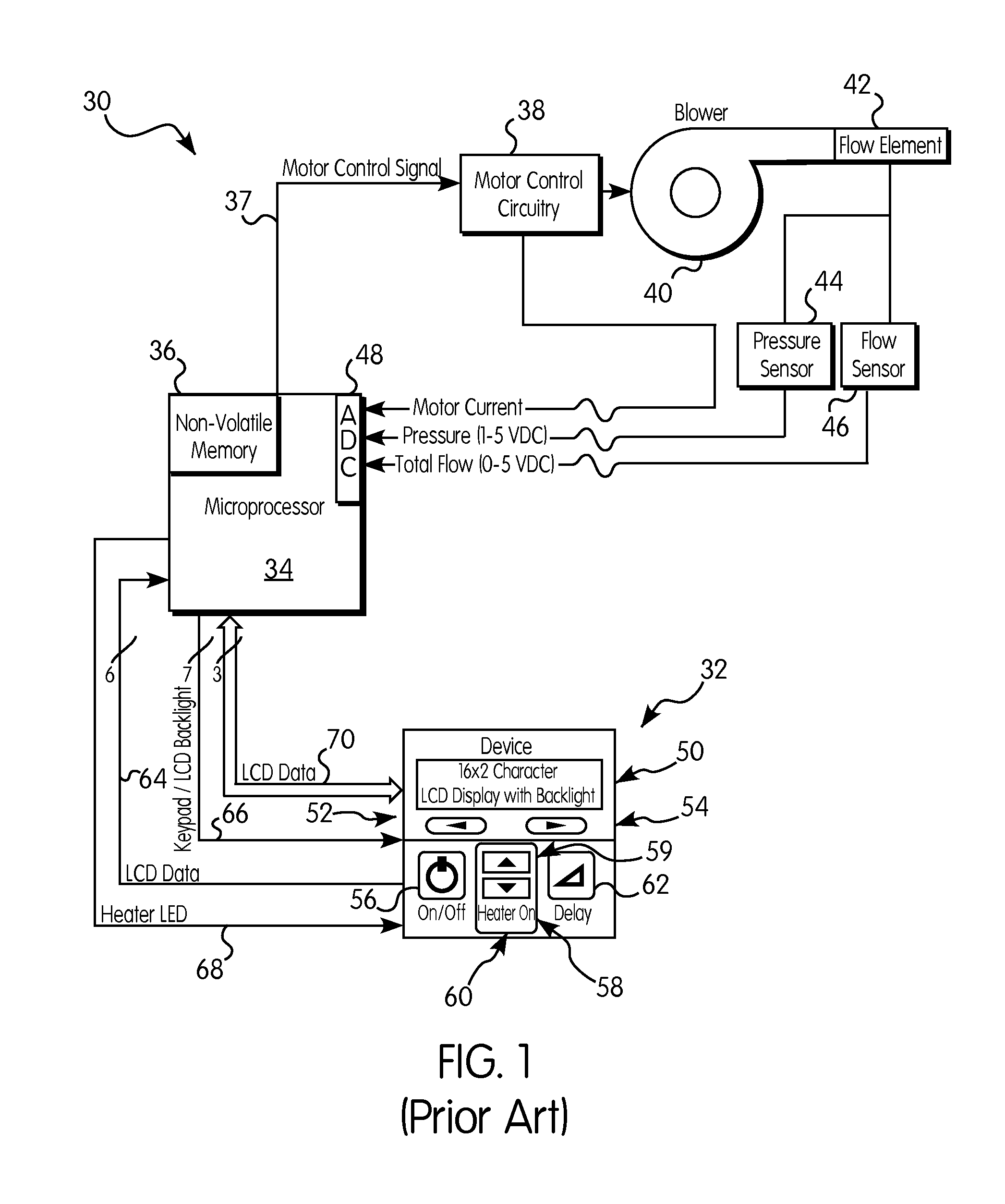
[0019]FIG. 1 is a block diagram of a typical breathing therapy device on which the present invention could be implemented. The device includes a main unit 30 housing microprocessor 34 and related non-volatile memory 36, as well as blower 40 and motor control circuitry 38. The device 30 is typically equipped with a user interface panel 32 which may be used to control the device as well as to program various operating parameters into the device.

[0020]Microprocessor 34 runs software stored in non-volatile memory 36, which implements the algorithms controlling blower 40 to regulate the pressure being delivered to the user of the device. The present invention could be implemented as a control algorithm stored as software in non-volatile memory 36 and executed by microprocessor 34.

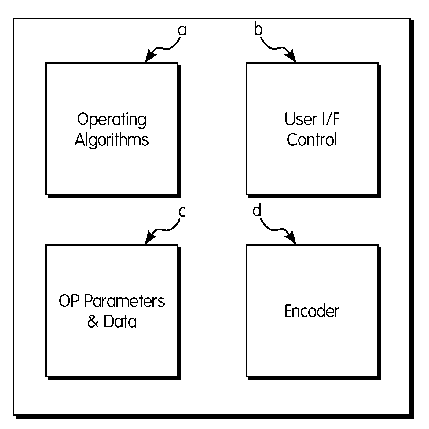
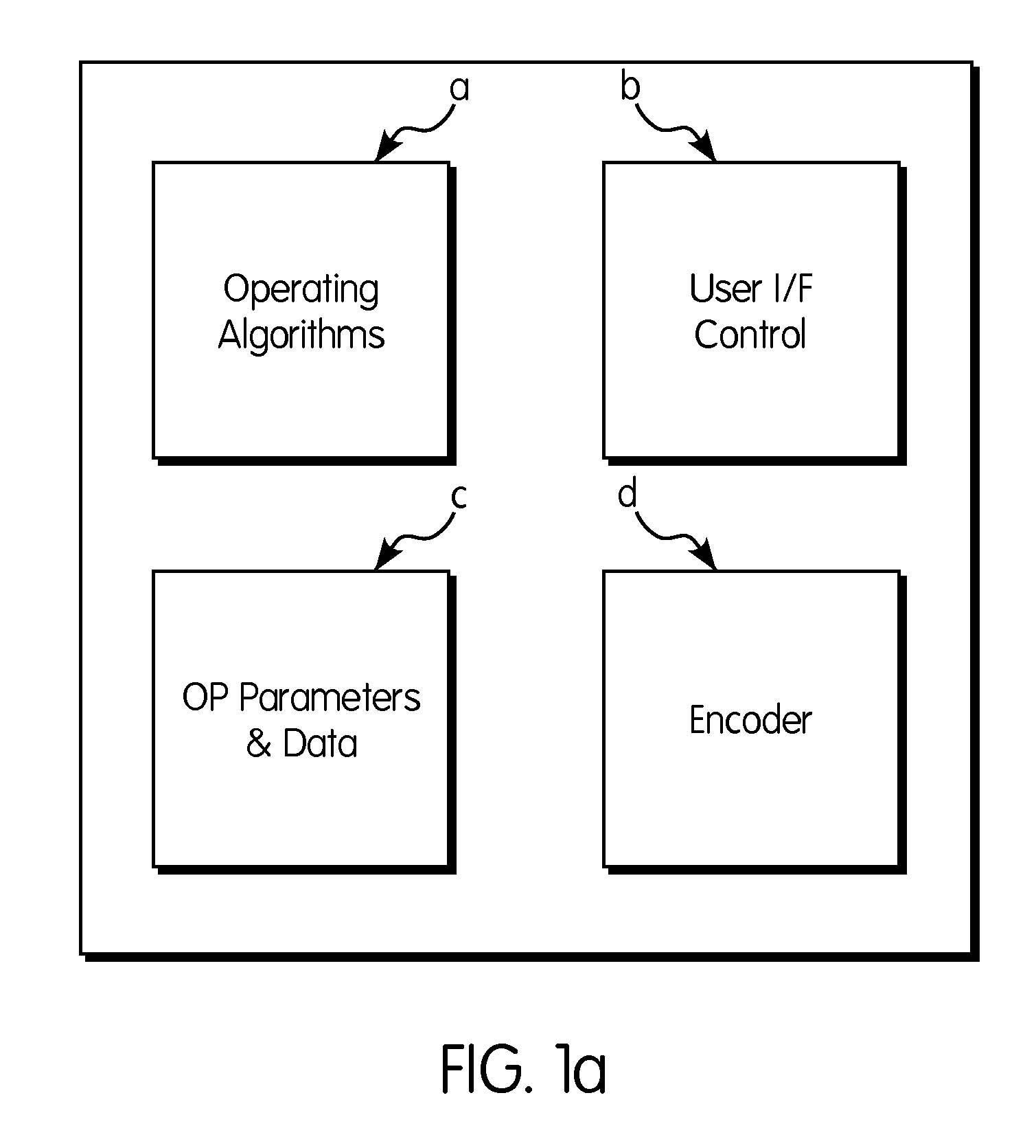
[0021]Microprocessor 34 and non-volatile memory 36 control the functioning of the unit. Non-volatile memory 36 may be broken down as shown in FIG. 1a and includes operating algorithms 36a, user interface control...


PUM


Abstract

A method for controlling the transitions between two different pressures supplied by a breathing therapy device using a transition pressure profile for which the basic shape, the magnitude and the duration may be controlled by a user of the device or the user's therapist.

Description

FIELD OF THE INVENTION[0001]This invention is related to the field of breathing gas delivery machines, such as continuous positive airway pressure (CPAP) or bi-level positive airway pressure (Bi-PAP) machines of the type typically used to treat patients suffering from breathing disorders, such as hypopnea or apnea, and, in particular, is related to controlling the shape of the curve representing the pressure delivered to the patient.BACKGROUND OF THE INVENTION[0002]Continuous Positive Airways Pressure (CPAP) machines are well known in the art for use in the treatment of a number of respiratory conditions, such as sleep apnea and hypopnea, by supplying a continuous positive pressure to a patient's airway while the patient sleeps. A typical CPAP apparatus is programmed with a CPAP therapy pressure, and is able to maintain the set pressure (measured either at the mask or at a base unit) during the inhalation and exhalation phases of the breathing cycle.[0003]In a variation of the basic...

Claims


Application Information

Patent Timeline
Patent Type & Authority Applications(United States)
IPC IPC(8): A61M16/00
CPCA61M16/0051A61M16/0066A61M2016/0021A61M2016/0027A61M16/0069A61M2016/0036A61M2205/3317A61M2205/502A61M2016/003A61M16/026
Inventor BORING, JOSEPH
Owner 3B MEDICAL INC
Why Eureka
Try Eureka