Damping structure

a technology of adamping structure and adamping axis, which is applied in the direction of shock absorbers, solid-based dampers, vibration suppression adjustments, etc., can solve the problems of reducing the efficiency of damping, so as to achieve the effect of reducing the elastic modulus, reducing the density, and reducing the need for vibration acceleration

Active Publication Date: 2012-02-02
KOBE STEEL LTD
View PDF2 Cites 10 Cited by
  • Summary
  • Abstract
  • Description
  • Claims
  • Application Information

AI Technical Summary

Benefits of technology

[0015]According to the damping structure of the invention, at least a part of the wall face parts of the hollow body vibrates more violently than the structure, on receiving the vibration. According to this structure, the powder / particle materials more violently move, as compared with a case where all the wall face parts vibrate integrally with the structure to be damped. As the results, mutual collisions, elastic deformations, and frictions are generated in the powder / particle materials, and the damping effect can be reliably realized, even against small vibration having vibration acceleration of less than 1 G.
[0016]Moreover, in this invention, in the case where the vibration wall face part is formed of the material having a lower elastic modulus and / or a lower density than the other parts of the hollow body, the vibration wall face part vibrates more violently than the structure to be damped, on receiving vibration. According to this structure, the powder / particle materials more violently move, as compared with a case where all the wall face parts vibrate integrally with the structure. As the results, mutual collisions, elastic deformations, and frictions are generated in the powder / particle materials, and the damping effect can be reliably realized, even against small vibration having vibration acceleration of less than 1 G.
[0017]Moreover, in this invention, in the case where the powder / particle materials are in contact with the vibration wall face part when the structure is not vibrating, the powder / particle materials reliably receive the vibration from the vibration wall face part when vibrating. As the results, the powder / particle materials violently move, and stabilized damping effect can be more reliably realized.
[0018]Moreover, in this invention, in the case where the powder / particle materials are in contact with both the vibration wall face part and the rigid wall face part when the structure is not vibrating, the powder / particle materials are reliably brought into contact with the vibration wall face part which is violently vibrating, and the rigid wall face part which is integrally vibrating with the structure to be damped when also vibrating. According to this structure, the powder / particle materials reliably receive the vibration from the vibration wall face part, and at the same time, the damping effect can be reliably transmitted to the wall face parts. As the results, stabilized damping effect can be more reliably realized.
[0019]Moreover, in this invention, in the case where the hollow body is mounted in a state where the rigid wall face part is in contact with the surface of the structure, since the damping member is mounted on the surface of the structure by way of the rigid wall face part, the damping effect can be reliably transmitted from the wall face part to the structure. Further, the hollow body can be stably mounted, and stabilized damping effect can be more reliably realized.
[0020]Moreover, in this invention, in the case where the vibration wall face part is formed in the wall face part which is not in parallel with the vibration direction of the structure, out of the wall face parts of the hollow body, excitation of the vibration wall face part is reliably realized, when the structure vibrates. As the results, stabilized damping effect can be more reliably realized.

Problems solved by technology

However, the damping effect by using the powder / particle materials has such a feature that it has non-linear characteristics, and therefore, there is a problem that by simply filling the cavities with the powder / particle materials, reliable damping effect cannot be obtained, depending on conditions.
Moreover, by adopting these techniques, sufficient damping effect cannot be obtained against vibrations with small amplitudes.
Therefore, there has been a problem that vibration acceleration of 1 G or more is required for obtaining the damping effect.

Method used


Image

  • Damping structure
  • Damping structure
  • Damping structure

Examples


examples

[0073]Now, the invention will be more specifically described by way of examples. However, the invention is not limited to the below described examples, but the invention can be carried out by appropriately adding modifications within a scope adaptable to the gist of the invention. Any of the modifications are included in a technical scope of the invention.

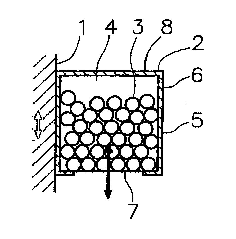
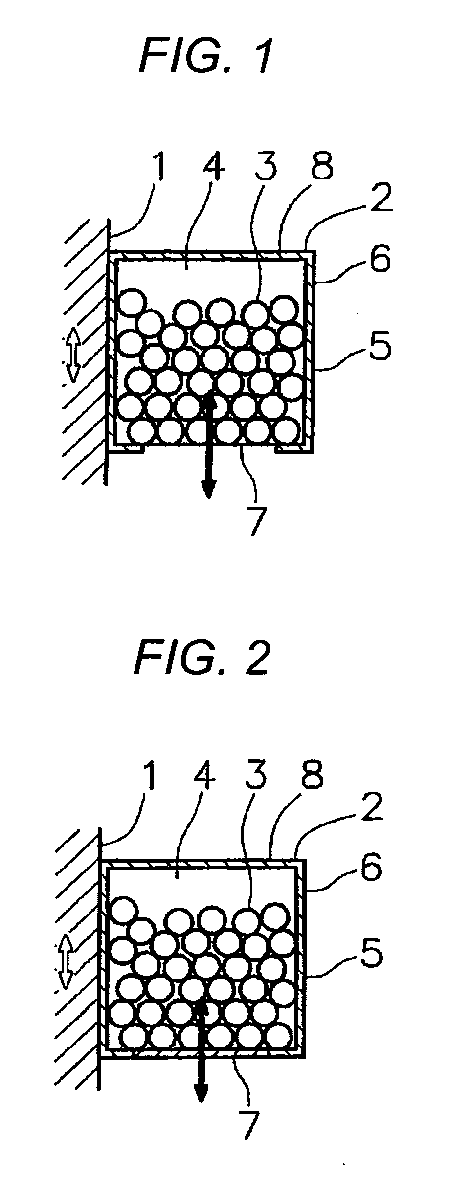
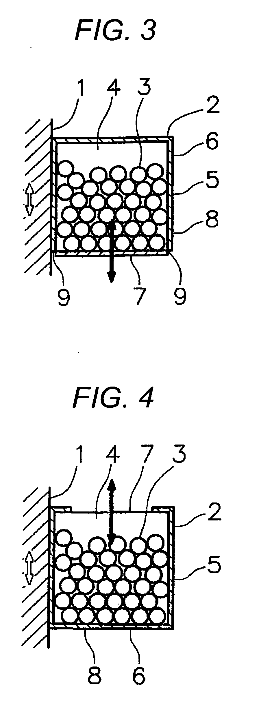
[0074]In this example, a hollow body 5 (damping member 2) filled with powder / particle materials 3 is mounted on the upper face of a structure 1 to be damped, which is perpendicular to a vibration direction of the structure 1 as shown by a bidirectional white arrow, in both an example of the invention as shown in FIGS. 19(a) and 19(b), and a comparative example as shown in FIGS. 20(a) and 20(b). It is to be noted that the powder / particle materials 3 are not shown in FIGS. 19 and 20.

[0075]In both the example of the invention and the comparative example, a space 4 inside the hollow body 5 is formed in a cubical shape having a size of ...


PUM


Abstract

According to the invention, there is provided a damping structure capable of obtaining a sufficient damping effect even against vibrations of small amplitudes, by promoting movements of powder/particle materials inside a hollow body. In the damping structure of the invention, a damping member 2 is provided on a structure 1 to be damped. The damping member 2 includes a hollow body 5 which is filled with powder/particle materials 3, partially leaving a space 4. A vibration wall face part 7 which vibrates more violently than the structure 1, on receiving vibration, is formed in at least a part of wall face parts 6 of the hollow body 5. The vibration wall face part 7 is preferably formed of a material having a lower elastic modulus and/or a lower density than the other parts.

Description

TECHNICAL FIELD[0001]The present invention relates to a damping structure which can be effectively used in a vibrating structure and the like.BACKGROUND ART[0002]A stator and a rotor of a motor or a generator, gears and rotation shafts of a reduction gear, beam members of a transport machine such as an automobile, a frame structure of a building, a large-sized mechanical structure, a structure for fixing the same, and so on generally vibrate. A damping technique for depressing vibration of such a structure, by providing a damping member having a hollow body in which powder / particle materials such as grain or powder are filled in a closed space, on the structure which is vibrating, has been already developed. This technique has been actually adopted, in a field where the vibration cannot be overcome by a technique using damping material such as elastic material or a vibration absorbing device, which has been heretofore widely employed. Such a technique has been proposed in Patent Doc...

Claims


Application Information

Patent Timeline
Patent Type & Authority Applications(United States)
IPC IPC(8): F16F9/30
CPCF16F15/363F16F7/015
Inventor TSUGIHASHI, KAZUKISUGIMOTO, AKIOYAMAGUCHI, ZENZOMASUDA, KYOKOYANO, YOSHIO
Owner KOBE STEEL LTD
Why Eureka
Try Eureka