
Electromechanically actuated membrane valve for branching ducts of sprinkling and/or weed control systems

a technology of electronic mechanical control and membrane valve, which is applied in the field of agriculture, can solve the problems of reducing the useful life of the membrane, particularly complex, and the resistance of the membrane, and achieves the effect of reducing the force, long-lasting and high-efficiency sealing elements

Inactive Publication Date: 2012-02-02
ARAG
View PDF13 Cites 4 Cited by
  • Summary
  • Abstract
  • Description
  • Claims
  • Application Information

AI Technical Summary

Benefits of technology

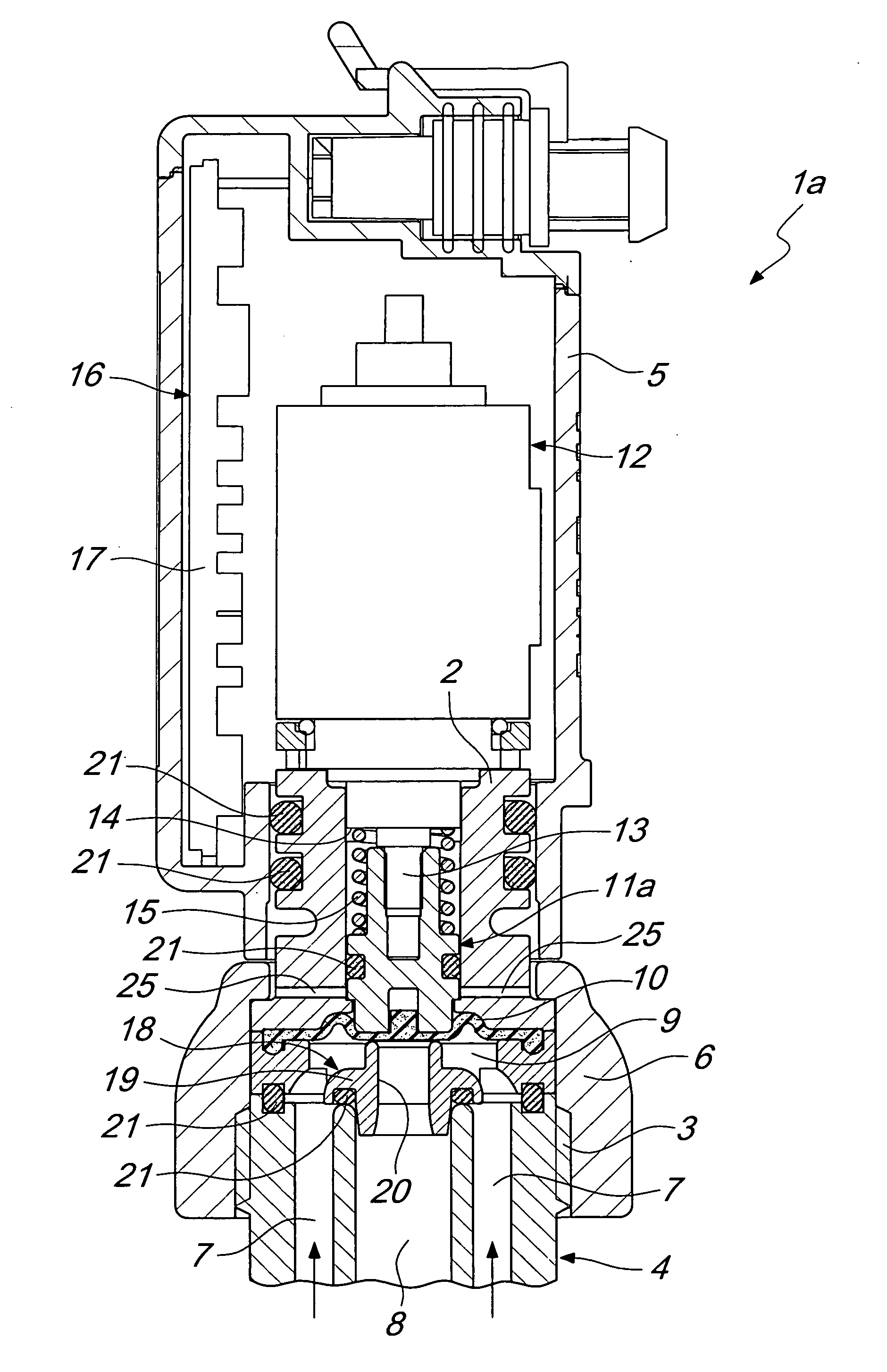
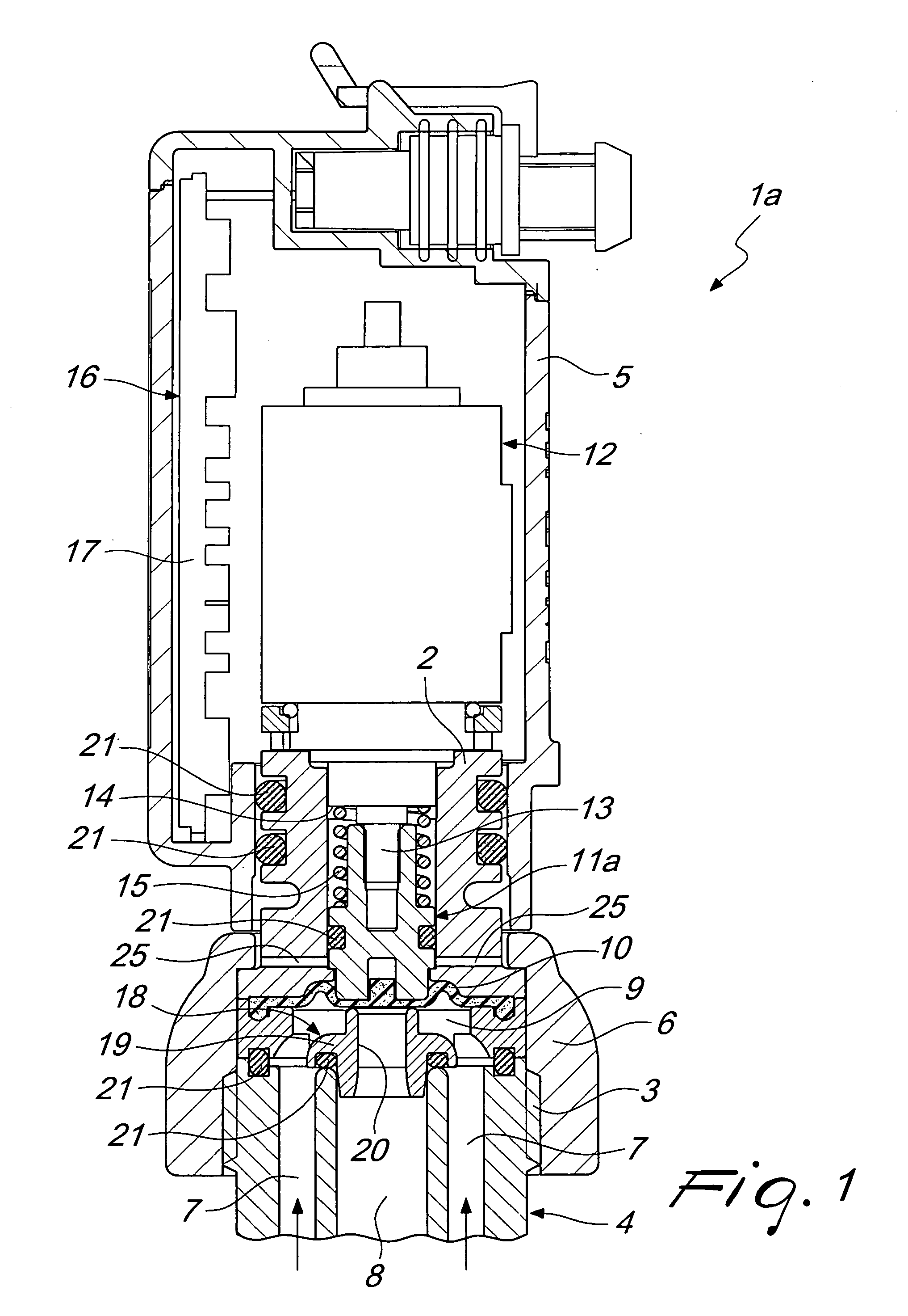
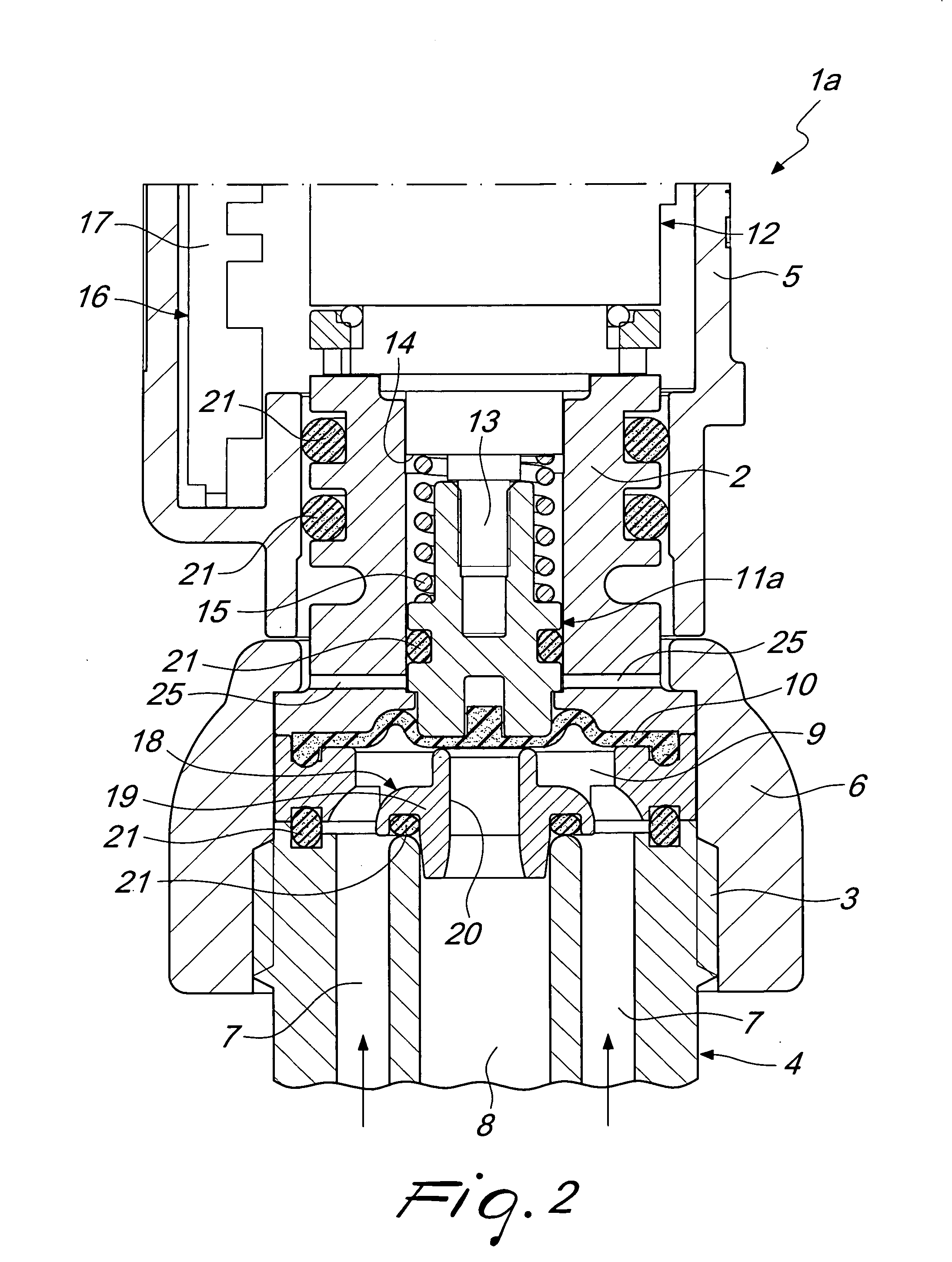
[0026]The aim of the present invention is to eliminate the above-mentioned drawbacks in the background art by providing an electromechanically actuated membrane valve, particularly for branching ducts of a fluid of sprinkling and / or weed control systems and the like, that makes it possible to ensure long-lasting and high efficiency of the sealing elements and, at the same time, a decrease in the force exerted to move the elements adapted to closing / opening the branching duct.
[0027]Within this aim, an object of the invention is to provide an electromechanically actuated membrane valve that enables considerable savings in terms of electricity absorbed for the operation thereof, especially in dispensing systems in which it is necessary to have a high number of valves, independent of each other and individually controlled.
[0029]A further object of the invention is to provide a valve that has low encumbrances, is easy to wire and assemble and is easily adapted to the applications in use and, therefore, universally usable.
[0030]Another object of the present invention is to provide an electromechanically actuated membrane valve, particularly for branching ducts of a fluid of sprinkling and / or weed control systems and the like, that has a simple structure, is easy and practical to implement, safe to use and effective in operation, and relatively low-cost.

Problems solved by technology

Electromechanically actuated valves of the known type are not devoid of drawbacks among which there is the fact that they are particularly complex, in that they are a combination of a plurality of constructive elements that are difficult to assemble, and in that they involve complicated calibration steps.
Moreover, a further drawback of electromechanically actuated valves of the known type consists in the fact that the need to have a through hole in the sealing element, i.e. the membrane, while on the one hand allowing the decreasing of the force that the solenoid has to exert to close the duct, on the other hand compromises the resistance of the membrane, thus drastically decreasing its useful lifetime and preventing the separation of the elements in motion and the elements responsible for the motion from the fluid to be dispensed, a fact that inevitably prejudices the operation and reliability of the valve over time.
This solution, however, has the drawback of not ensuring a perfect seal and a separation of the elements in motion, i.e. the piston, and the elements responsible for the motion, i.e. the linear actuator, springs and others, from the fluid to be dispensed due to the absence of the membrane.

Method used


Image

  • Electromechanically actuated membrane valve for branching ducts of sprinkling and/or weed control systems
  • Electromechanically actuated membrane valve for branching ducts of sprinkling and/or weed control systems
  • Electromechanically actuated membrane valve for branching ducts of sprinkling and/or weed control systems

Examples


second embodiment

[0046]With reference to the second embodiment, shown in FIGS. 4 to 6, as will be better described hereinafter, for preventing unwanted dripping of the fluid intercepted by the valve 1b, the piston 11b is provided by a first part 22 associated with the movable element 13 of the electromechanical actuator 12 and a second part 23 designed to engage the disk-like membrane 10.

[0047]Advantageously, the first part 22 and the second part 23 are mutually associated by a mating of the snap-acting type with second elastic means 24 interposed consisting, for example, in a preloaded second helical spring adapted to send the second part 23 into contact with the disk-like membrane 10 thus closing the valve 1b after a lowering of the pressure of the fluid coming from the external duct 7 below a preset value of, for example, 0.5 bar.

[0048]Moreover, in both of the embodiments proposed, an aeration system is provided consisting in at least one venting hole 25, preferably two on opposite sides, of smal...

first embodiment

[0056]With regard to the first embodiment only, given the use for which the valve 1a is designed, in order to prevent unwanted dripping of the fluid, it is preferable, in the absence of electricity, for the movable element 13 to be arrangeable in its extracted position by the electromechanical actuator 12 so as to switch the valve 1a to its closed configuration, i.e. send the piston 11a into abutment with the perforated bushing 19 with the disk-like membrane 10 interposed between the two.

[0057]The anti-drip system just described can be implemented if the electromechanical actuator 12 is not of the stepped motor type. In fact, if an electromechanical actuator 12 of the stepped motor type is used, the movement of the movable element 13 of the electromechanical actuator 12 is made possible only by electrically actuating the electromechanical actuator 12.

[0058]Differently, in the second embodiment, notwithstanding the use of stepped motors to provide the electromechanical actuator 12 in...


PUM


Abstract

An electromechanically actuated membrane valve, for branching ducts of sprinkling and / or weed control systems, comprising a hollow valve body associated with an end portion of a branching duct of a fluid that contains a piston adapted to interact with a disk-like membrane for blocking the end portion of the branching duct.The piston is movable in the valve body between an open configuration and a closed configuration of the valve. The branching duct comprises an internal duct and an external duct which are mutually coaxial.A passage section reduction element for the internal duct is provided associated with the valve body to interact with the disk-like membrane for the hermetic isolation of the internal duct with respect to the external duct and vice versa.

Description

[0001]The present invention relates to an electromechanically actuated membrane valve, particularly for branching ducts of a fluid of sprinkling and / or weed control systems and the like.BACKGROUND OF THE INVENTION[0002]In the field of agriculture and, in particular, with regard to sprinkling techniques, it is known to use sprinkler machines designed to accurately distribute irrigation liquids over the ground, such as fertilizers, fluids for herbicide treatments, anticryptogamics, insecticides, pesticides, water and other liquids.[0003]More precisely, sprinkler machines of the known type, which are generally fixed or pulled by a tractor that travels over the crop to be sprinkled, are basically constituted by a chassis supporting a tank filled with the fluid to be sprinkled and associated with a pumping assembly that supplies one or more sprinkler bars used to distribute the fluid.[0004]Going further into detail, sprinkler bars of the known type, which can be of the horizontal type fo...

Claims


Application Information

Patent Timeline
Patent Type & Authority Applications(United States)
IPC IPC(8): F16K31/02
CPCF16K27/0236F16K27/029F16K31/0672
Inventor SCHIAVONE, MARIOGUBERTINI, FRANCESCO
Owner ARAG
Learn More