Communications device for performing wireless communications, wireless communications system, wireless communications method, and storage medium

a technology for wireless communication and communication devices, applied in power management, wireless commuication services, high-level techniques, etc., can solve the problems of increasing the burden on users, affecting the use and being unfavorable. to achieve the effect of improving the usability of communications devices configured with a power-saving mod

Inactive Publication Date: 2012-02-02
BUFFALO CORP LTD
View PDF6 Cites 28 Cited by
  • Summary
  • Abstract
  • Description
  • Claims
  • Application Information

AI Technical Summary

Benefits of technology

[0007]An object of the present invention, brought about taking the above-described factors into consideration, is to ma

Problems solved by technology

However, communications devices configured with a power-saving mode risk being inadequately convenient.
For example, a user using a terminal device to attempt to carry out wireless communications with an access p

Method used


Image

  • Communications device for performing wireless communications, wireless communications system, wireless communications method, and storage medium
  • Communications device for performing wireless communications, wireless communications system, wireless communications method, and storage medium
  • Communications device for performing wireless communications, wireless communications system, wireless communications method, and storage medium

Examples


first embodiment

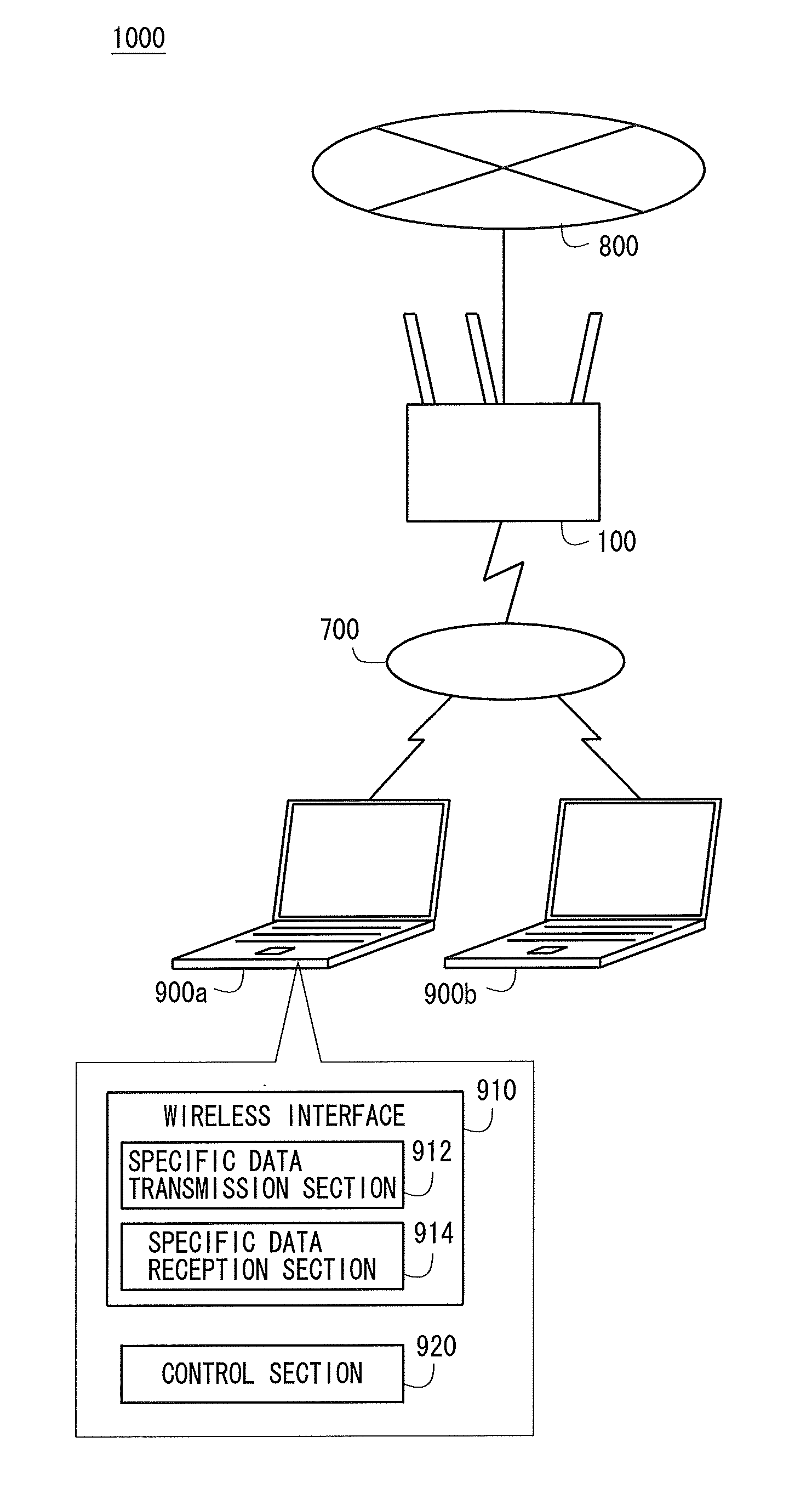
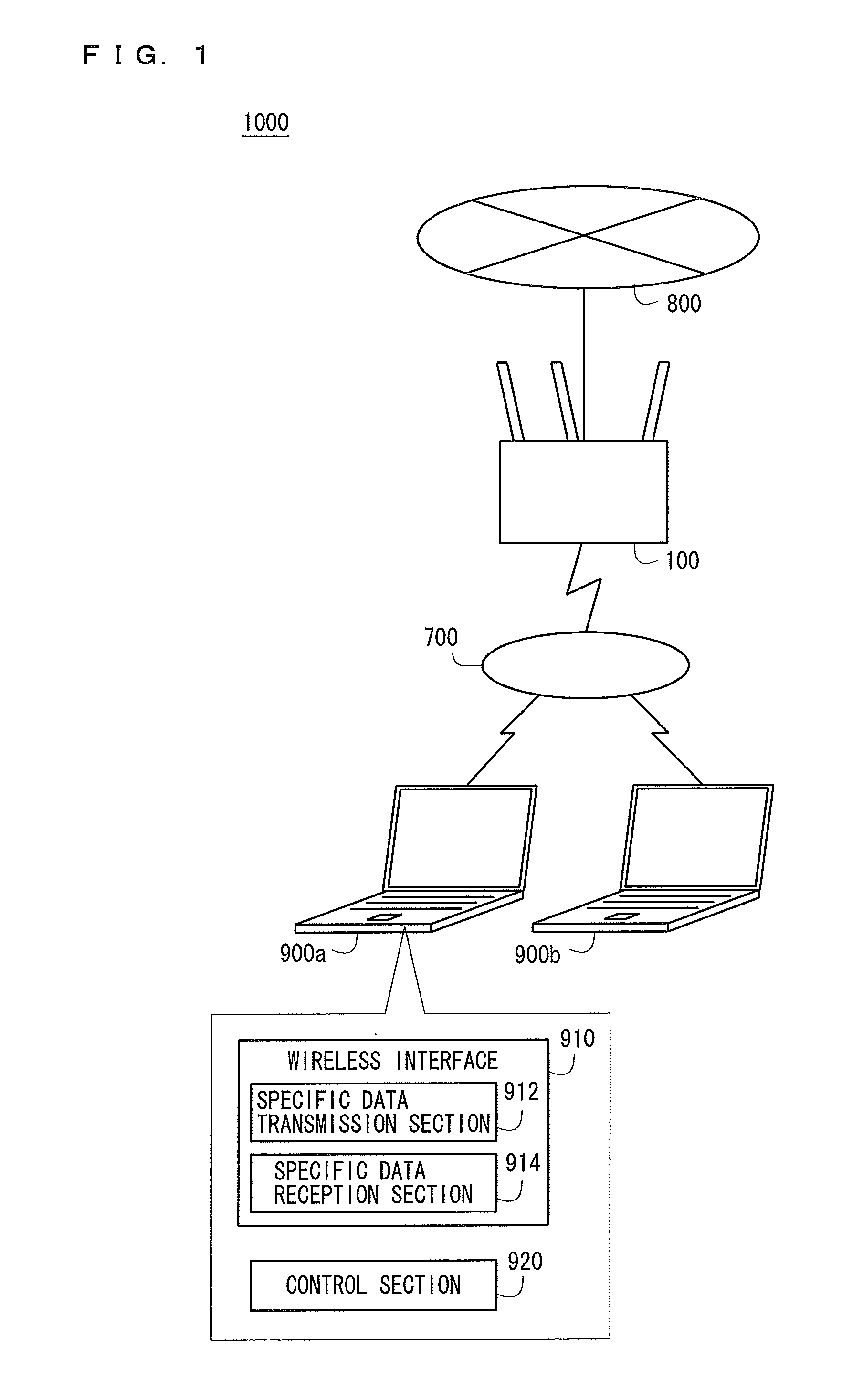
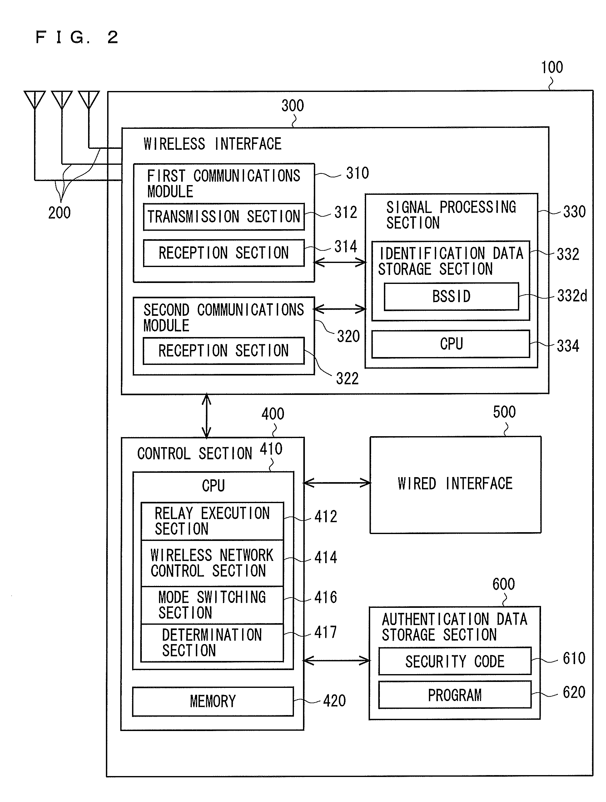
[0029]A configuration of a first embodiment will be described. FIG. 1 is a diagram illustrating a network system 1000 according to the present embodiment. The network system 1000 includes: a relay device 100, which is a first communications device; a network 800, which is wire-connected to the relay device 100; and wireless communications terminals 900a and 900b, which are second communications devices connecting to the relay device 100 by wireless communications. The network 800 is a so-called LAN (local area network), and is connected to the Internet via a not-illustrated router. The relay device 100, and the wireless communications terminals 900a and 900b are each a wireless LAN communications device compliant with, for example, the Institute of Electrical and Electronics Engineers (IEEE) 802.11n standard. The relay device 100 and the wireless communications terminals 900a and 900b may be compliant with any of the IEEE 802.11a, b, and g standards. Further, the relay device 100 an...

second embodiment

[0082]A structure of a second embodiment will be described. FIG. 5 is a block diagram illustrating a configuration of a relay device 100A in a network system according to the present embodiment. The relay device 100A in the network system of the present embodiment is different from the relay device 100 of the first embodiment in that, in the relay device 100A, the CPU 410 of the control section 400 includes a decryption section 418. The components of the relay device 100A other than the decryption section 418 are the same as those of the relay device 100 according to the first embodiment. Further, in the network system of the present embodiment, the control section 920 of the wireless communications terminal 900a (FIG. 1) includes an encryption section (illustration omitted) for encrypting data in a predetermined encryption method. The configuration of the network system of the present embodiment other than the difference described above is the same as that of the network system 100...

third embodiment

[0095]A configuration of a third embodiment will be described. FIG. 7 is a block diagram illustrating a configuration of a relay device 100B in a network system according to the present embodiment. The relay device 100B of the network system of the present embodiment is different from the relay device 100 of the first embodiment in that the mode switching section 416 of the third embodiment has a function different from that of the mode switching section 416 of the first embodiment, and the wireless interface 300 of the relay device 100B does not include the second communications module 320. The components of the relay device 100B of the present embodiment other than the difference described above are the same as the components of the relay device 100 of the first embodiment. The configuration of the network system of the present embodiment other than the relay device 100B is the same as that of the network system 1000 of the first embodiment. The difference from the first embodimen...


PUM


Abstract

A communications device for performing wireless communications includes: a data receiving section for receiving data by wireless communications; a data transmitting section for transmitting data by wireless communications; a mode switching section for switching an operation mode of the communications device between a first mode in which power is supplied to the data transmitting section, and a second mode in which power consumption in at least the data transmitting section is minimized over that in the first mode; and a determination section for determining whether the data receiving section has received designated data. The mode switching section switches the operation mode of the communications device from the second mode to the first mode if, in a state in which the communications device is in the second mode, the determination section has determined that the data receiving section has received the designated data.

Description

CROSS REFERENCE TO RELATED APPLICATION[0001]The disclosure of Japanese Patent Application No. 2010-171810, filed on Jul. 30, 2010, is incorporated herein by reference.BACKGROUND OF THE INVENTION[0002]1. Field of the Invention[0003]The present invention relates to communications devices for performing wireless communications.[0004]2. Description of the Background Art[0005]Wireless communications systems whereby wireless communications among a plurality of communications devices are carried out are known. In such wireless communications systems, as disclosed in, for example, Japanese Laid-Open Patent Publication No. 2005-109850, access points and terminal devices that are non-access-point stations are used as the communications devices, to perform wireless communications between the access points and the terminal devices. In such wireless communications systems, the communications devices in some instances are configured with a mode for minimizing power consumption (power-saving mode)...

Claims


Application Information

Patent Timeline
IPC IPC(8): H04W88/02H04W88/08
CPCH04B1/406H04B7/15557H04W12/06Y02B60/50H04W84/047H04W88/06H04W52/0274Y02D30/70
Inventor YAMAGUCHI, SATORU
Owner BUFFALO CORP LTD
Why Eureka
Try Eureka