
System for actively monitoring wear on wind turbine brake pads and related methods

a technology for actively monitoring and brake pads, which is applied in the direction of liquid fuel engines, vessel construction, marine propulsion, etc., can solve the problems of significant damage to the wind turbine brake system, high cost and time-consuming inspection methods, and general wear and tear of the brake pads over tim

Active Publication Date: 2012-02-02
GENERAL ELECTRIC CO
View PDF7 Cites 33 Cited by
  • Summary
  • Abstract
  • Description
  • Claims
  • Application Information

AI Technical Summary

Benefits of technology

[0010]These and other features, aspects and advantages of the present invention will become better understood with reference to the following description and appended claims. The accompanying drawings, which are incorporated in and constitute a part of this specification, illustrate embodiments of the invention and, together with the description, serve to explain the principles of the invention.

Problems solved by technology

Due to the frictional sliding between the brake pads and the yaw bearing, the pads generally wear over time.
Unfortunately, this inspection method is very expensive and time consuming.
Additionally, since the inspection method requires that the wind turbine be shutdown, such inspections are typically performed only at normal maintenance intervals.
Thus, wear issues occurring between the maintenance intervals go unnoticed, which can lead to significant damage to the wind turbine brake system.

Method used


Image

  • System for actively monitoring wear on wind turbine brake pads and related methods
  • System for actively monitoring wear on wind turbine brake pads and related methods
  • System for actively monitoring wear on wind turbine brake pads and related methods

Examples


Embodiment Construction

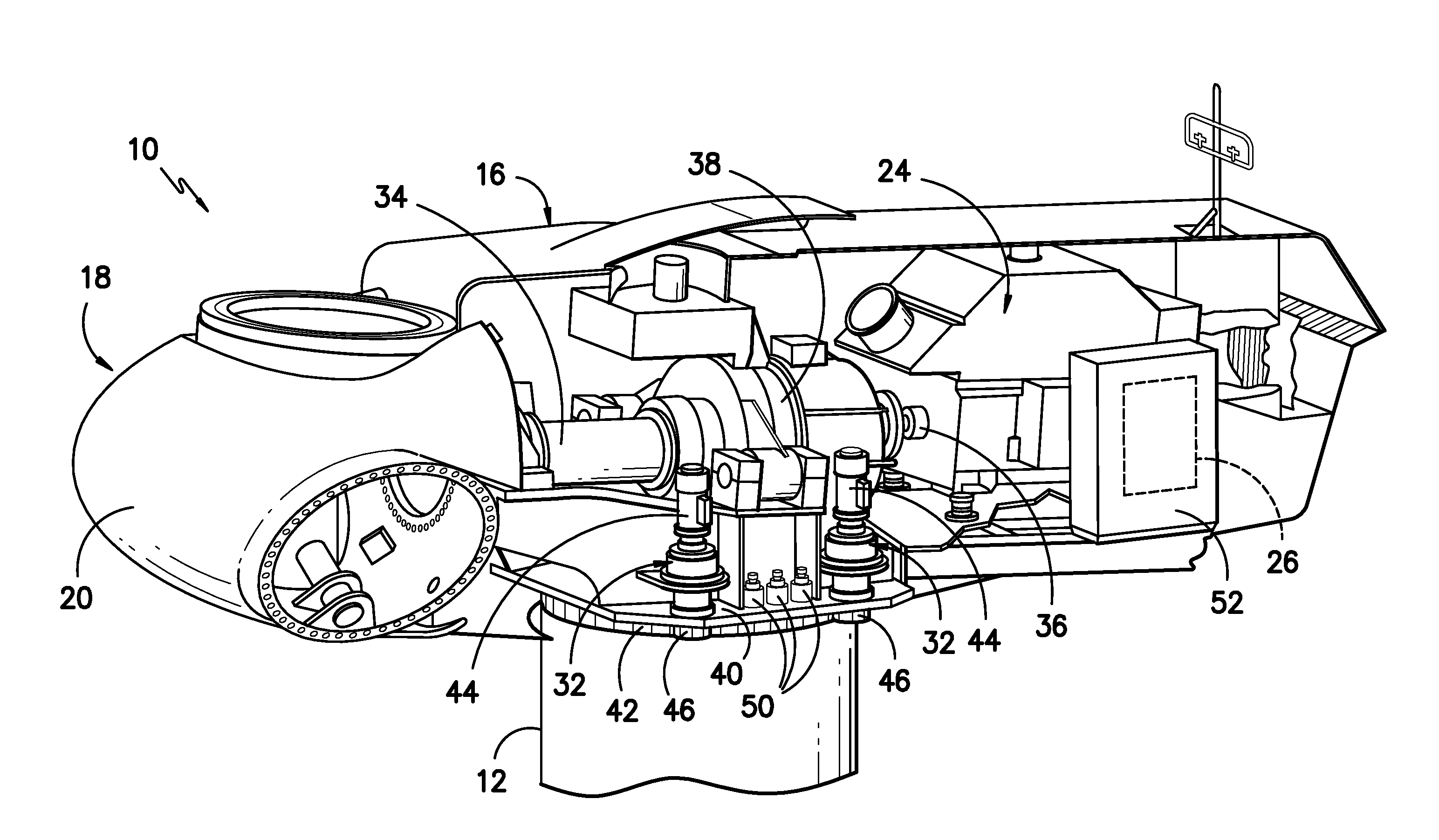
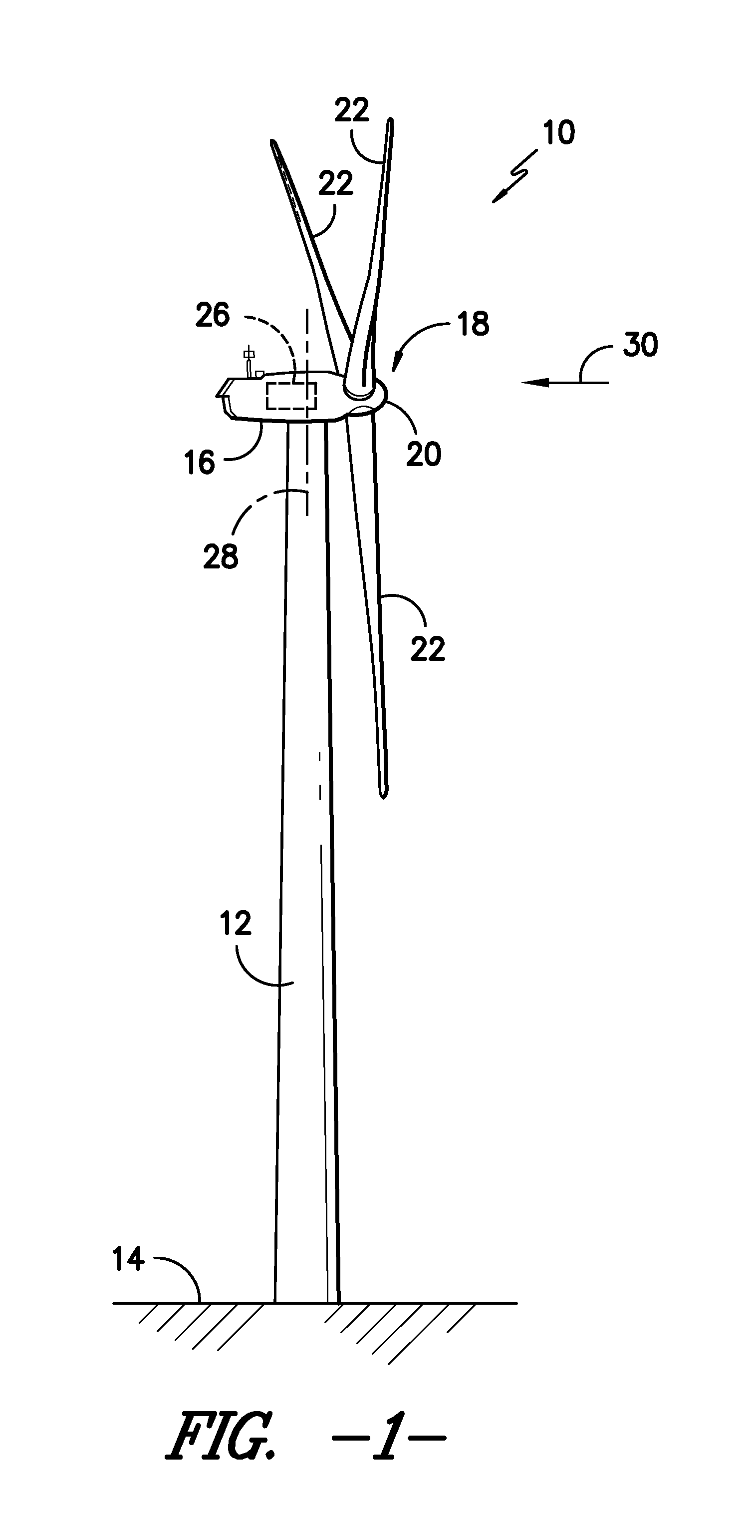
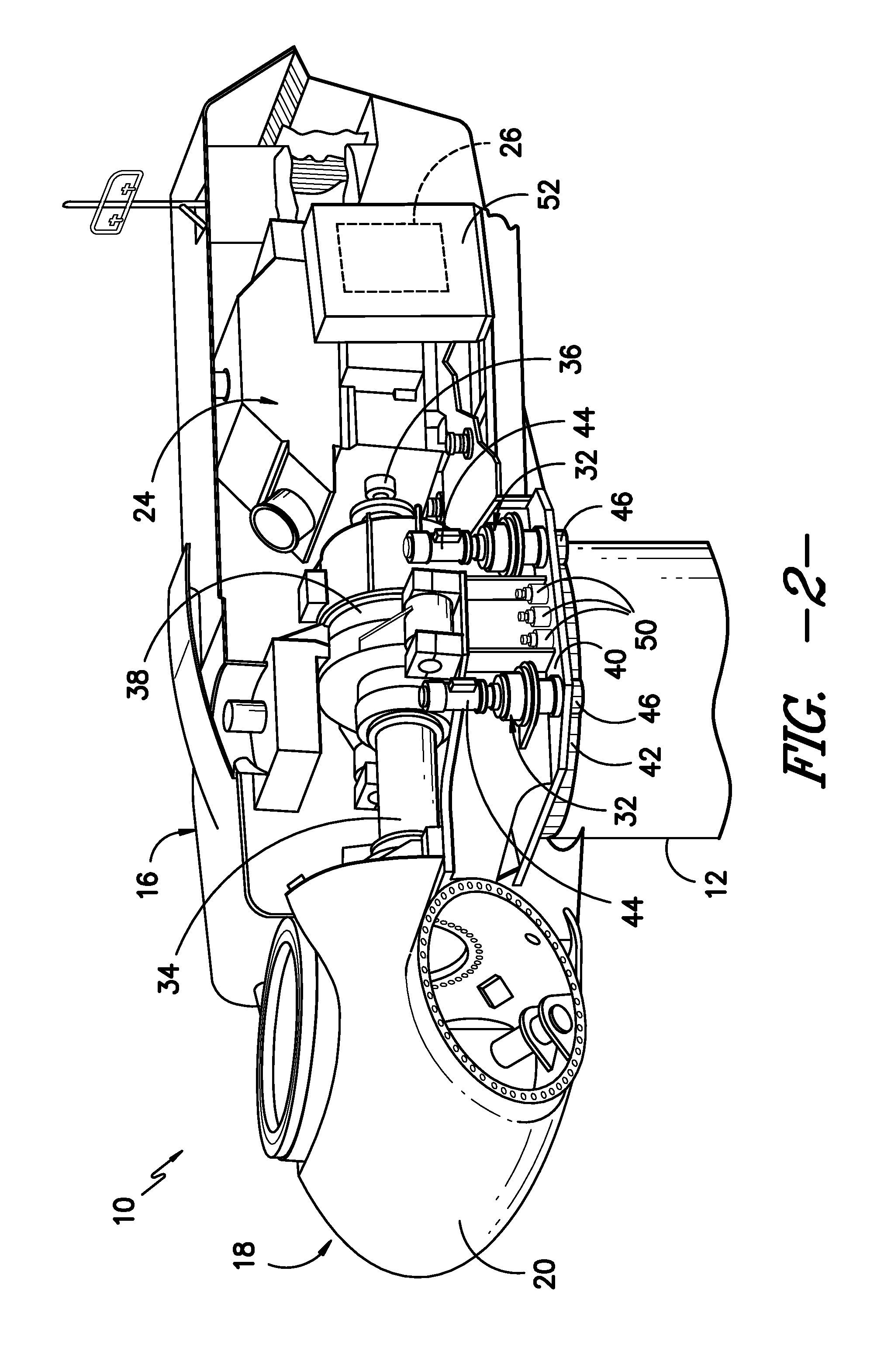
[0020]Reference now will be made in detail to embodiments of the invention, one or more examples of which are illustrated in the drawings. Each example is provided by way of explanation of the invention, not limitation of the invention. In fact, it will be apparent to those skilled in the art that various modifications and variations can be made in the present invention without departing from the scope or spirit of the invention. For instance, features illustrated or described as part of one embodiment can be used with another embodiment to yield a still further embodiment. Thus, it is intended that the present invention covers such modifications and variations as come within the scope of the appended claims and their equivalents.

[0021]In general, the present subject matter is directed to a system for actively monitoring wear on a brake pad of a brake assembly of a wind turbine. For example, in several embodiments, the system may include a monitoring device configured to detect brak...


PUM


Abstract

A system for monitoring wear on a brake pad of a wind turbine is disclosed. The system may include a brake assembly having a brake pad and a moveable component. The brake pad may be configured to engage a friction surface of the wind turbine. The movable component may be configured to move relative to the friction surface as the brake pad wears. Additionally, the system may include a sensor at least partially mounted within the brake assembly. The sensor may be configured to detect a position of the movable component relative to the sensor or a position of the friction surface relative to the sensor.

Description

FIELD OF THE INVENTION[0001]The present subject matter relates generally to braking systems for wind turbines and, more particularly, to a system and method for actively monitoring wear on a brake pad of a wind turbine.BACKGROUND OF THE INVENTION[0002]Generally, a wind turbine includes a tower, a nacelle mounted on the tower, and a rotor coupled to the nacelle. The rotor typically includes a rotatable hub and a plurality of rotor blades coupled to and extending outwardly from the hub. Each rotor blade may be spaced about the hub so as to facilitate rotating the rotor to enable kinetic energy to be transferred from the wind into usable mechanical energy, and subsequently, electrical energy.[0003]To properly orient the rotor blades relative to the direction of the wind, wind turbines typically include one or more yaw drive mechanisms configured to engage a yaw bearing for rotating the nacelle relative to the tower. Additionally, to control such rotation, a wind turbine may include one...

Claims


Application Information

Patent Timeline
IPC IPC(8): F03D11/00
CPCF03D11/0091F05B2260/902Y02E10/726F16D66/026Y02E10/722F16D66/025F03D17/00Y02E10/72
Inventor DANIELS, JEFFREY MICHAELNEUMANN, ULRICH
Owner GENERAL ELECTRIC CO
Learn More