Broadcasting method and radio apparatus

Inactive Publication Date: 2012-02-02
PANASONIC INTELLECTUAL PROPERTY MANAGEMENT CO LTD
View PDF6 Cites 21 Cited by
  • Summary
  • Abstract
  • Description
  • Claims
  • Application Information

AI Technical Summary

Benefits of technology

[0010]The present invention reduces the influence by

Problems solved by technology

Such a road-to-vehicle communication requires installation o

Method used


Image

  • Broadcasting method and radio apparatus
  • Broadcasting method and radio apparatus
  • Broadcasting method and radio apparatus

Examples


Example

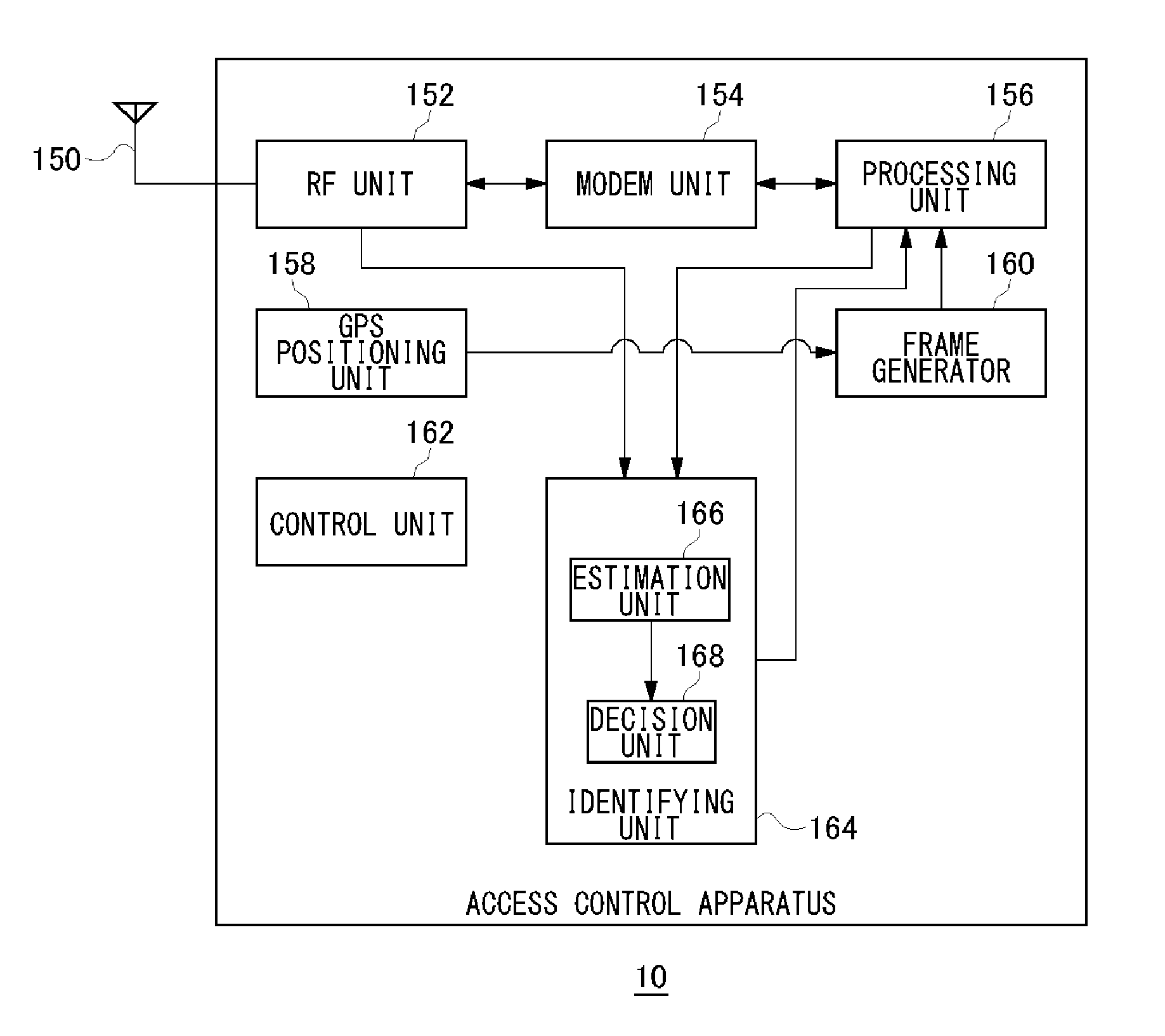
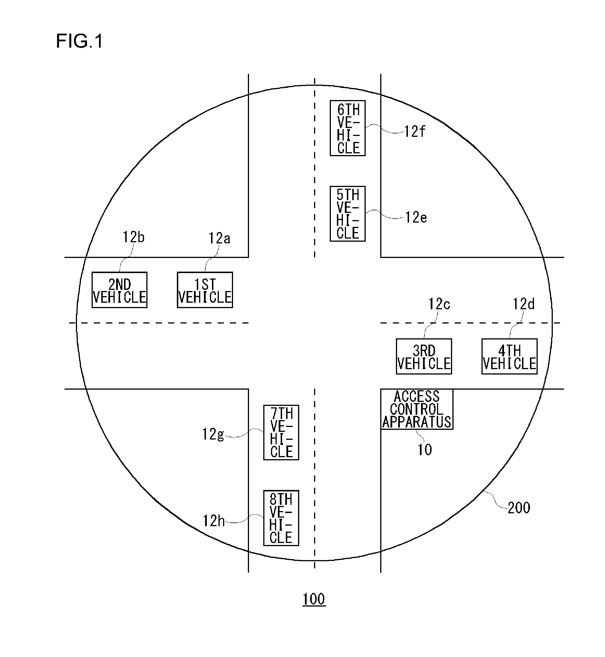
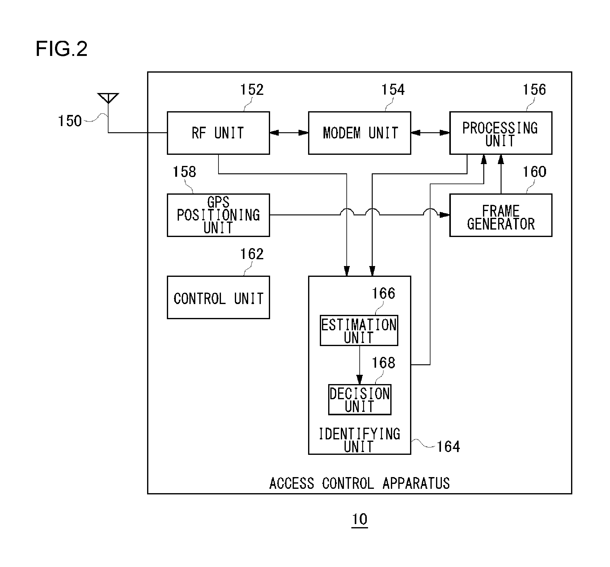
[0039]The present invention will be outlined before it is explained in detail. Exemplary embodiments of the present invention relate to a communication system carrying out data communication between terminal apparatuses installed in vehicles. A terminal apparatus transmits, by broadcast, packet signals containing information such as the traveling speed and position of a vehicle (hereinafter referred to as “data”). And the other terminal apparatuses receive the packet signals and recognize the approach or the like of the vehicle based on the data. Note here that the terminal apparatuses employ the OFDM modulation scheme to achieve faster communication speed. Under these circumstances, an increase in the number of terminal apparatuses at an intersection or like place increases the probability of packet signals occurring. To cope with it, the communication system according to the present exemplary embodiment executes the following processes.

[0040]The communication system according to t...


PUM


Abstract

An RF unit receives periodically signals broadcast by other terminal apparatuses. When the quality of the signal received periodically is more deteriorated than a second threshold value even though the intensity of the signal received periodically is larger than a first threshold value, an identifying unit detects a malfunction in another terminal apparatus from which the signal received periodically by the receiver has been broadcast. A processing unit, a modem unit, the RF unit and an antenna each broadcasts a signal containing the detection result that the malfunction has been detected and information on a detected location.

Description

TECHNICAL FIELD[0001]The present invention relates to a broadcasting technology and, more particularly, to a broadcasting method for sending signals containing predetermined information and a radio apparatus.BACKGROUND TECHNOLOGY[0002]Road-to-vehicle communication has been under investigation in an effort to prevent collision accidents of vehicles on a sudden encounter at an intersection. In a road-to-vehicle communication, information on conditions at an intersection is communicated between a roadside unit and an in-vehicle unit. Such a road-to-vehicle communication requires installation of roadside units, which means a great cost of time and money. In contrast to this, a vehicle-to-vehicle (inter-vehicular) communication, in which information is communicated between in-vehicle units, has no need for installation of roadside units. In that case, current position information is detected in real time by GPS (Global Positioning System) or the like and the position information is excha...

Claims


Application Information

Patent Timeline
IPC IPC(8): H04W88/02H04B17/00H04B17/17H04J11/00H04M1/00H04W4/44H04W24/00H04W24/08
CPCH04L27/2602H04W4/04H04B17/309H04W88/02H04W24/06H04W4/44
Inventor NAGAI, MAKOTONAKAOKA, KENKAWASE, KUNIHIRO
Owner PANASONIC INTELLECTUAL PROPERTY MANAGEMENT CO LTD
Why Eureka
Try Eureka