System and method for robot trajectory generation with continuous accelerations

a robot trajectory and continuous acceleration technology, applied in the field of robots, can solve the problems of inability to calculate the inverse jacobian, and the joint acceleration calculation method based on the inverse jacobian matrix also failed at singular configurations

Inactive Publication Date: 2012-02-02
INST OF AUTOMATION CHINESE ACAD OF SCI
View PDF1 Cites 25 Cited by
  • Summary
  • Abstract
  • Description
  • Claims
  • Application Information

AI Technical Summary

Benefits of technology

[0014]The invention has wide applications which can be used in on-line trajectory planning as well as off-line mode; and it can be utilized in the situation without known velocities when robot is at singular configurations (taking the place of SPLINE 1 method) as well as the situation with known velocities of all path points (replacing PVT method). In this invention, the accelerations at all path points on trajectory are continuous and controllable, jerky motions and system vibrations caused by discontinuity and uncontrolled acceleration can be settled effectively.

Problems solved by technology

However it is unable to calculate the inverse Jacobian matrix sometimes when any two joint axes of a 6-dof (degree of freedom) robot come to one line.
Moreover the joint acceleration calculation methods based on inverse Jacobian matrix also failed at singular configurations.
However the control accuracy of the velocity on trajectory is worse.
On the other hand, PVT method needs to know the position and velocity at all path points, the control accuracy of which is higher than Spline1 method, but it cannot deal with the situation when robot is at singular configurations.
However these curve interpolation methods mentioned above have not taken into account the acceleration of all path points.
As for robot motion control, jerky motions and system vibrations tend to be caused by discontinuity and uncontrolled acceleration.

Method used


Image

  • System and method for robot trajectory generation with continuous accelerations
  • System and method for robot trajectory generation with continuous accelerations
  • System and method for robot trajectory generation with continuous accelerations

Examples


case 1

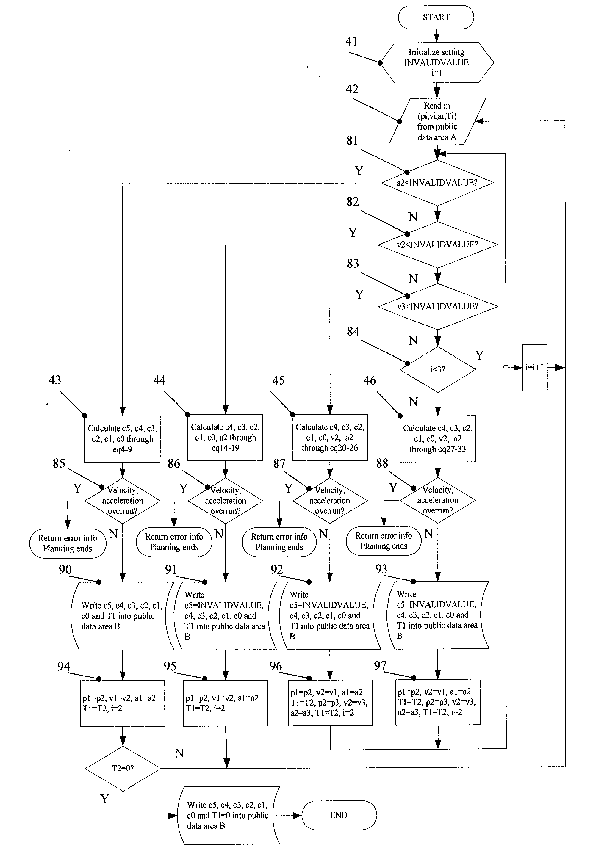
acceleration of the second path point a2 is valid (Module 81), Module 43 is invoked, and a quintic polynomial is used to describe position, see eq. 1; then a quartic polynomial is used to describe velocity, see eq. 2; and a cubic polynomial is used to describe acceleration, see eq. 3. ‘u’ in each formula is a normalized time variable, whose definition is in eq. 10. Eq. 2 is the derivative of eq. 1 with respect to ‘u’, and eq. 3 is the derivative of eq. 2 with respect to ‘u’. The parameters (c5,c4,c3,c2,c1,c0) in eq. 1-3 can be calculated by eq. 4-9, respectively. Velocity and acceleration verification Module 85 is used to calculate the maximum velocity vmax and acceleration amax within [0,1] through eq. 2 and eq. 3, comparing vmax and amax with the velocity's limit value and acceleration's limit value in Robot Parameter Database 13, respectively. If vmax exceeds velocity's limit value or amax exceeds acceleration's limit value, the interpolation is finished, and error message is ret...

case 2

acceleration of the second path point a2 is invalid, while the velocity v2 is valid (Module 82), Module 44 is invoked, and a quartic polynomial is used to describe position, see eq. 11; then a cubic polynomial is used to describe velocity, see eq. 12; and a quadratic polynomial is used to describe acceleration, see eq. 13. ‘u’ in each formula is a normalized time variable, whose definition is in eq. 10. Eq. 12 is the derivative of eq. 11 with respect to ‘u’, and eq. 13 is the derivative of eq. 12 with respect to ‘u’. The parameters (c4, c3, c2, c1, c0) in eq. 11-13 can be calculated by eq. 14-18, respectively. a2 can be calculated by eq. 19 to substitute for the invalid number in (p2,v2,a2,T2). Velocity and acceleration verification Module 86 is used to calculate the maximum velocity vmax and acceleration amax within [0,1] through eq. 12 and eq. 13, comparing vmax and amax with the velocity's limit value and acceleration's limit value in Robot Parameter Database 13, respectively. If...

case 3

velocity of the second path point v2 is invalid (Module 83), then data of third path point is read in to form data set [(p1,v1,a1,T1), (p2,v2,a2,T2), (p3,v3,a3,T3)], while v3 is valid. Module 45 is invoked, and a quartic polynomial is used to describe the position of trajectory curve connecting the first path point and the second path point, such as eq. 11; then a cubic polynomial is used to describe the velocity of trajectory curve connecting the first path point and the second path point, such as eq. 12; and a quadratic polynomial is used to describe the acceleration of trajectory curve connecting the first path point and the second path point, such as eq. 13. ‘u’ in each formula is a normalized time variable, whose definition is in eq. 10. Eq. 12 is the derivative of eq. 11 with respect to ‘u’ and eq. 13 is the derivative of eq. 12 with respect to ‘u’. The parameters (c4, c3, c2, c1, c0) in eq. 11-13 can be calculated by eq. 20-24, respectively. v2 can be calculated by eq. 25 and...


PUM


Abstract

A method for robot trajectory generation with continuous acceleration, Receiving a user's motion command through a motion command interface, and sending the user's motion command to Cartesian trajectory generator; Converting the user's command to a trajectory path points of robot end effector in Cartesian space; Transforming the trajectory path points of robot end effector in Cartesian space into a robot trajectory path points in a joint space; Calculating positions, velocities and accelerations of robot joints in each motion servo cycle; Comparing the positions, velocities and accelerations of the robot joints generated by a joint Trajectory Interpolator with a velocity's limit value and an acceleration's limit value of each robot joint stored in a robot parameter database respectively.

Description

FIELD OF THE INVENTION[0001]The present invention relates to robot, especially to a system and method for generating robotic manipulator trajectories.BACKGROUND OF THE INVENTION[0002]Industrial robot accomplishes tasks through the movement of its end effector in Cartesian space, which cannot be controlled directly. It has to be realized by controlling the robot joints' motion. The position, velocity and acceleration of each joint determine the pose, velocity and acceleration as well as the trajectory of end effector at any time. Therefore, in order to perform Cartesian control of end-effector's pose, velocity and acceleration at each moment, the position, velocity and acceleration of each joint in every servo period have to be controlled, which is the purpose of trajectory generation.[0003]The trajectory of robot end effector defines a set of discrete path points consisted of pose, velocity and acceleration at certain intervals in Cartesian space. As described above, all the path po...

Claims


Application Information

Patent Timeline
Patent Type & Authority Applications(United States)
IPC IPC(8): G05B15/00
CPCB25J9/1664G05B2219/43062G05B2219/40519G05B2219/40454
Inventor JING, FENGSHUITAN, MINLI, ENLIANG, ZIZEHOU, ZENGGUANGYANG, DEGANGZHANG, KAILIANGQIANG, YANHUI
Owner INST OF AUTOMATION CHINESE ACAD OF SCI
Why Eureka
Try Eureka